Friction-type stud shearing-force connection part and construction method thereof

A connector and stud technology, applied in the field of shear connectors and their construction, can solve the problems of shear failure of connectors, increased construction difficulty, and increased engineering costs, so as to achieve controlled shear bearing capacity and improved transmission. force mode for precise control of the effect

Inactive Publication Date: 2018-01-30
HOHAI UNIV
View PDF5 Cites 6 Cited by
  • Summary
  • Abstract
  • Description
  • Claims
  • Application Information

AI Technical Summary

Problems solved by technology

However, the shear connectors that need to be welded at the position where the shear force is large are dense, and the amount of steel used is greatly increased, as shown in Figure 1, which significantly increases the project cost and increases the difficulty of construction; There are generally three-level welds between the connecting parts, and the welding quality is not easy to guarantee. The welding process makes the steel subject to high temperature stress, resulting in adverse effects such as welding residual stress and local buckling.
For the support section of multi-span continuous girder bridge, the contact section of cable and bridge deck of cable-stayed suspension bridge, the transition section of long-span load-bearing composite structure and other negative bending moment areas, as well as the concrete stress caused by shrinkage, creep and temperature effects In the area, due to the restraint effect of traditional s

Method used


Image

  • Friction-type stud shearing-force connection part and construction method thereof
  • Friction-type stud shearing-force connection part and construction method thereof
  • Friction-type stud shearing-force connection part and construction method thereof

Examples


Example Embodiment

[0053] The technical solution of the present invention will be described in detail below in conjunction with the drawings.

[0054] Figure 1a with Figure 1b A schematic diagram of a stud shear connector provided for a beam or plate in the prior art. The figure shows that the shear connector needs to be welded to the beam or plate, which is labor-intensive and wastes materials.
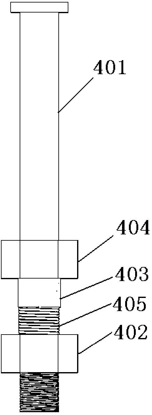
[0055] Such as Figure 2-Figure 4 Shown is a friction-type stud shear connector, which includes a stud shear connector body 401, a mounting nut 402, a sleeve 403, a fixing nut 404, and a semiconductor spring 405. The stud shear connector body consists of From bottom to top, it includes a threaded section 4001, a threadless extrusion section 4002, and an anti-pull pier 4003. The upper end surface of the fixing nut is at the top of the threaded section and is welded to the main body of the stud shear connector. The upper end of the sleeve is welded to the lower end of the fixing nut. The semiconductor spri...


PUM


Abstract

The invention discloses a friction-type stud shearing-force connection part and a construction method thereof. The friction-type stud shearing-force connection part includes a stud shearing-force connection part main body, a mounting nut, a sleeve, a fixing nut and a semiconductor spring; the stud shearing-force connection part main body comprises a thread section, a thread-free extrusion sectionand a pulling-resistant pier in sequence from bottom to top; during factory prefabrication, the stud shearing-force connection part main body is sleeved with the fixing nut, the sleeve and the semiconductor spring from the thread section in sequence, the upper end face of the fixing nut is located at the top of the thread section and is fixed, the upper end of the sleeve is fixed to the lower endface of the fixing nut, the upper end of the semiconductor spring and the lower end of the sleeve are connected into one, and the shearing-force connection parts are mounted on a maim beam at intervals according to needed shearing resistant requirements. By the adoption of the friction-type stud shearing-force connection part and the construction method thereof, force transferring modes of traditional shearing force connection parts are improved, interface friction is reasonably utilized, the pretension force of the friction-type stud shearing-force connection part can be monitored and controlled, and the design philosophy of combining resistance and releasement can be achieved. The factory prefabrication degree is high, bolt splicing is conducted on the spot, and the labor cost is saved.

Description

technical field [0001] The invention relates to a shear connector and a construction method thereof, in particular to a friction type stud shear connector and a construction method thereof. Background technique [0002] There are two types of shear connectors in steel structures or steel and concrete composite structures: stud shear connectors and section steel shear connectors. They have two main functions: (1) Shear resistance: bear the two materials of steel and concrete The longitudinal shear stress between the interfaces restricts the longitudinal free sliding between the two interfaces, thereby ensuring the cooperative deformation and working together of the combined structure, and improving the stiffness and bearing capacity of the combined structure. (2) Pull-out resistance: Shear connectors are generally provided with pier heads or curling edges on the side deep into the concrete to make them tightly bite with the concrete and resist the detachment of the two materi...

Claims


Application Information

Patent Timeline
IPC IPC(8): E01D19/00E01D21/00
Inventor 伍凯南洋陈峰林诗琪翟江棚
Owner HOHAI UNIV
Why Eureka
Try Eureka