Shearing-resistant and not-pull-resistant friction-type shearing force connection part and construction method thereof

A technology of connectors and components, which is applied in the direction of architecture and building construction, etc., can solve the problems of composite structure system performance, long-term performance and durability adverse effects, concrete internal force cannot be released, cannot be deformed or slipped, etc., to avoid direct Damage, changes in shear capacity and stiffness, effects of a high degree of prefabrication

Active Publication Date: 2018-01-30
HOHAI UNIV
View PDF10 Cites 3 Cited by
  • Summary
  • Abstract
  • Description
  • Claims
  • Application Information

AI Technical Summary

Problems solved by technology

However, in the negative bending moment area, local stress concentration area, and transition area, etc., the combined action between steel and concrete will make the composite member in an unfavorable state where the concrete is under tension and the steel is under compression.
[0006] In addition, the tensile stress in concrete caused by shrinkage, creep and temperature effects cannot be effectively released due to the constraints of traditional shear connectors, which will adversely affect the performance, long-term performance and durability of the composite structural system
This is caused by two reasons: 1. Traditional shear connectors are mainly "resistance", and cannot deform or slide with the deformation of concrete while transmitting shear force; 2. The traditional shear connectors The embedding effect between the pier head or the flange edge and the concrete is too strong, so that the internal force of the concrete cannot be released

Method used


Image

  • Shearing-resistant and not-pull-resistant friction-type shearing force connection part and construction method thereof
  • Shearing-resistant and not-pull-resistant friction-type shearing force connection part and construction method thereof
  • Shearing-resistant and not-pull-resistant friction-type shearing force connection part and construction method thereof

Examples


Embodiment Construction

[0056] The technical solution of the present invention will be described in detail below in conjunction with the drawings.

[0057] Figure 1a with Figure 1b A schematic diagram of a stud shear connector provided for a beam or plate in the prior art. The figure shows that the shear connector needs to be welded to the beam or plate, which is labor-intensive and wastes materials.

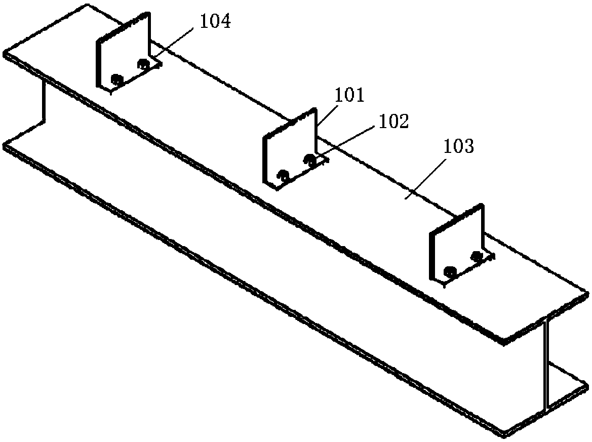
[0058] Such as figure 2 Shown is a friction-type shear connector, which includes a connector body 101 and a high-strength bolt assembly 102. The connector body is installed on the H-shaped steel main beam 103 through a high-strength bolt assembly, and the bolt holes 104 are long bolt holes. . The main girder can be replaced with any section steel or between the plates where shear connectors are needed. Install the main body of the connector on the H-shaped steel main beam at intervals according to the required shear resistance. The main body of the connector is an angle steel, which does not have an em...


PUM


Abstract

The invention discloses a shearing-resistant and not-pull-resistant friction-type shearing force connection part and a construction method thereof. The shearing force connection part includes a shearing force connection part main body and a high-strength bolt assembly; the shearing force connection part main body is angle steel, a plurality of bolt holes matched with the high-strength bolt assembly are formed in one flange edge, and the shearing force connection part main body is connected with a main beam through the high-strength bolt assembly. According to the shearing-resistant and not-pull-resistant shearing force connection part, force transferring modes of traditional shearing force connection parts are improved, interface friction between the shearing force connection part main body and a plate is reasonably utilized, bolts are reasonably designed, shearing force of the bolts can be monitored and controlled in real time, the factory prefabrication degree is high, bolt splicingis conducted on the spot, and therefore the labor cost is saved. The shearing-resistant and not-pull-resistant friction-type shearing force connection part is not provided with a fixed end and has theeffects of being resistant to shearing and not resistant to pulling.

Description

Technical field [0001] The invention relates to a shear connector and a construction method thereof, in particular to a shear-resistant-non-pulling friction type shear connector and a construction method thereof. Background technique [0002] In the steel-concrete composite structure, the shear connector is the key element to ensure that steel and concrete work together. The stud and the steel shear connector are currently widely used connector forms. The main function of these two connectors is to resist The shearing force and lifting (separation) between steel and concrete is a kind of "shear resistance" and "pulling resistance" connection, which limits the slippage between steel and concrete. [0003] The connection of "shear resistance" and "pulling resistance" can play the combined effect of the positive bending moment area of ​​the traditional steel-concrete composite structure and improve the bearing capacity and stiffness. For the negative moment area of ​​the composite st...

Claims


Application Information

Patent Timeline
Patent Type & Authority Applications(China)
IPC IPC(8): E04B1/48E04B1/49
Inventor 伍凯南洋陈峰徐超李辉
Owner HOHAI UNIV
Why Eureka
Try Eureka