Fuel cell power generation system, and fuel cell power generation interrupting method

A fuel cell and power generation system technology, applied in the direction of fuel cells, fuel cell additives, electrochemical generators, etc., can solve the problems of increasing operating costs, increasing the initial cost of machines, etc.

Inactive Publication Date: 2003-07-23
PANASONIC CORP
View PDF1 Cites 16 Cited by
  • Summary
  • Abstract
  • Description
  • Claims
  • Application Information

AI Technical Summary

Problems solved by technology

[0006] In the conventional fuel cell power generation system, it is necessary to have a nitrogen device 16 such as a nitrogen cylinder for nitrogen purge operation. For example, when it is used for household stationary distributed power generation and electric vehicle power supply, etc., there is an increase in the need for a large space. The question of the initial cost of the machine
In addition, there is a problem of increased operating costs due to the need to periodically replace and replenish nitrogen gas cylinders

Method used


Image

  • Fuel cell power generation system, and fuel cell power generation interrupting method
  • Fuel cell power generation system, and fuel cell power generation interrupting method
  • Fuel cell power generation system, and fuel cell power generation interrupting method

Examples


Embodiment approach 1

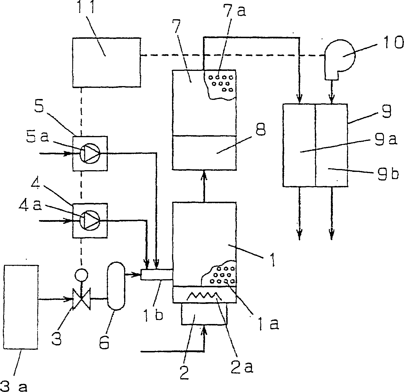
[0047] figure 1 It is a system configuration diagram of the fuel cell power generation system according to Embodiment 1 of the present invention. 1 is a reformer filled with a reforming catalyst 1a for reforming reaction. In the reformer 1, a burner 2a as a heating device 2 is provided, and at the inlet of the upstream 1b of the reformer 1, a raw material gas supply valve 3 is provided, and a water supply device 4 connected to the upstream 1b is provided. Water pump 4a and air pump 5a as air supply device 5 . Furthermore, between the upstream 1b of the reformer 1 and the raw material gas supply valve 3, a desulfurizer 6 for removing sulfur components contained in the raw material gas may be provided. And 3 a is a supply device for supplying raw material gas to the reformer 1 .

[0048] 7 is a carbon monoxide remover connected to the downstream of the reformer 1, and filled with a catalyst 7a for causing a carbon monoxide removal reaction. Between the reformer 1 and the ca...

Embodiment approach 2

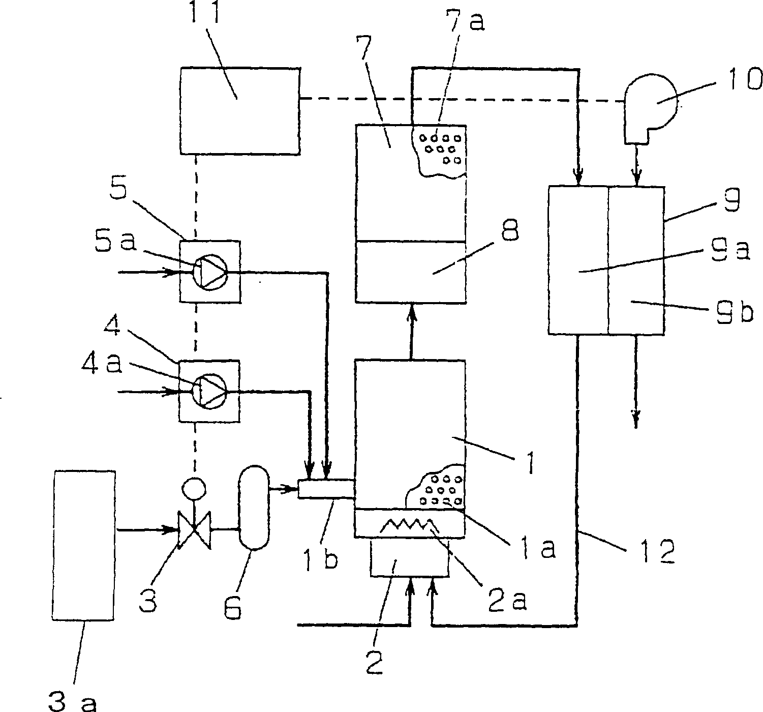
[0060] figure 2 It is a system configuration diagram of the fuel cell power generation system in Embodiment 2 of the present invention. The same symbols are used for the same parts as those in Embodiment 1, and descriptions of these parts are omitted. 12 is a hydrogen discharge connection for supplying waste hydrogen gas discharged from the hydrogen electrode 9a of the fuel cell 9 to the burner 2a.

[0061] Next, the operation of the second embodiment will be described.

[0062] Although most of the hydrogen gas is consumed by the power generation reaction in the hydrogen electrode 9a of the fuel cell 9, a certain amount of hydrogen gas is discharged as waste hydrogen gas. The waste hydrogen is sent into the burner 2a through the hydrogen exhaust connection 12, and is used as fuel to achieve effective utilization, and at the same time, the residual hydrogen is completely burned without being discharged to the outside.

[0063] In the second embodiment, when the power gener...

Embodiment approach 3

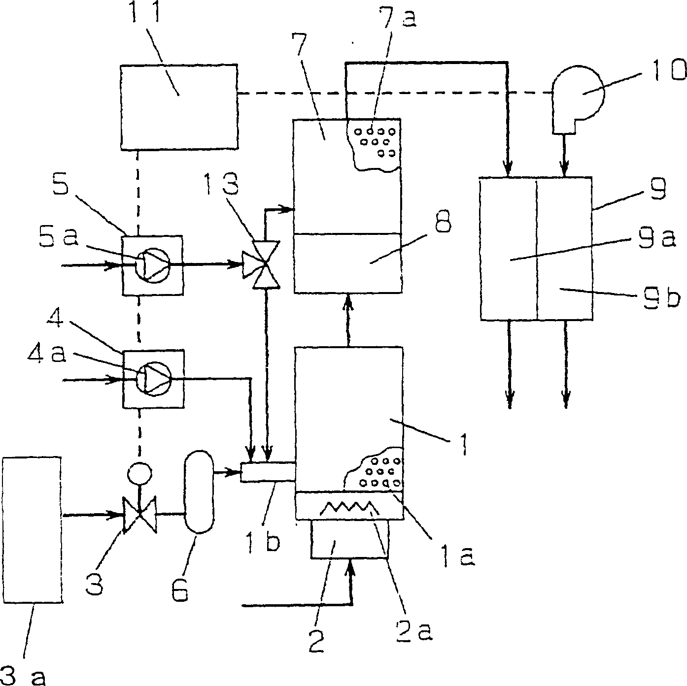
[0067] image 3 is a system configuration diagram of a fuel cell power generation system according to Embodiment 3 of the present invention. The same symbols are used for the same parts as those in Embodiment 1, and descriptions of these parts are omitted. In Embodiment 3, the carbon monoxide remover 7 adopts a selective oxidation trans type that selectively reacts carbon monoxide and air. Although usually in the case of selecting the oxidation method, it is necessary to supply air to carbon monoxide, the air pump 5a as the air supply device 5 also serves as an air supply device, and the switching device 13 switches the air to supply or supply to the carbon monoxide remover 7 as appropriate. It is supplied to the upstream stream 1b of the reformer 1.

[0068] Next, the operation of the third embodiment will be described. In this embodiment, when the power generation operation is stopped, the air pump 5a is used to supply the air for purging water vapor as in the first embod...


PUM


Abstract

A fuel cell electric power generating system is provided which does not occupy a large space, which requires a lower initial cost for equipment than the prior art, and of which the running cost is low. The system includes a reformer 1 producing hydrogen-rich gas by utilizing a source gas, source gas supplying means 3a of supplying the source gas to the reformer 1, air supplying means 5 of supplying purging air to the reformer, and a fuel cell 9 generating electric power by utilizing the hydrogen-rich gas produced at the reformer 1 and air for electric power generation supplied from outside, wherein in stopping the operation of the fuel cell 9, the supply of the source gas to the reformer 1 is stopped and the hydrogen-rich gas remaining within the fuel cell electric power generating system, steam and the purging air are passed in this order.

Description

technical field [0001] The invention relates to a fuel cell power generation system. Background technique [0002] So far, the fuel cell power generation system has a structure disclosed in Japanese Patent Application Laid-Open No. 3-257762, such as Figure 4 shown. That is, a reformer 1 for generating hydrogen-rich gas from a raw material gas, a burner 2a as a heating device 2 for heating the reformer, a nitrogen supply pipe 14 upstream of the reformer 1, and a shutoff valve 14 are provided with the reformer. The connected nitrogen equipment 16, the fuel cell 9 connected to the reformer through the reformed gas supply pipe 17 located downstream of the reformer 1, the fuel cell 9 generates electricity by reacting the oxygen in the air with the hydrogen produced , the downflow of the hydrogen electrode 9a side of the fuel cell 9 is connected to the burner 2a through the hydrogen exhaust connection 12 . The entire content of Japanese Patent Application Laid-Open No. 3-257762...

Claims


Application Information

Patent Timeline
Patent Type & Authority Applications(China)
IPC IPC(8): H01M8/04H01M8/06
CPCH01M8/0612H01M8/04022H01M8/0668H01M8/04223Y02E60/50H01M8/0675H01M8/04231H01M8/04303H01M8/04228H01M8/04H01M8/06
Inventor 上田哲也富泽猛鹈饲邦弘
Owner PANASONIC CORP
Why Eureka
Try Eureka