Method and apparatus for generating range subject distance image

A scene and distance technology, applied in the field of systems that generate three-dimensional images, can solve problems such as inability to determine various targets or different positions

Inactive Publication Date: 2003-08-20
MAJKROSOFT INT KHLDGZ
View PDF1 Cites 22 Cited by
  • Summary
  • Abstract
  • Description
  • Claims
  • Application Information

AI Technical Summary

Problems solved by technology

The camera cannot determine various targets or different positions within a certain range

Method used


Image

  • Method and apparatus for generating range subject distance image
  • Method and apparatus for generating range subject distance image
  • Method and apparatus for generating range subject distance image

Examples


Embodiment Construction

[0135] DETAILED DESCRIPTION OF THE PREFERRED EMBODIMENT

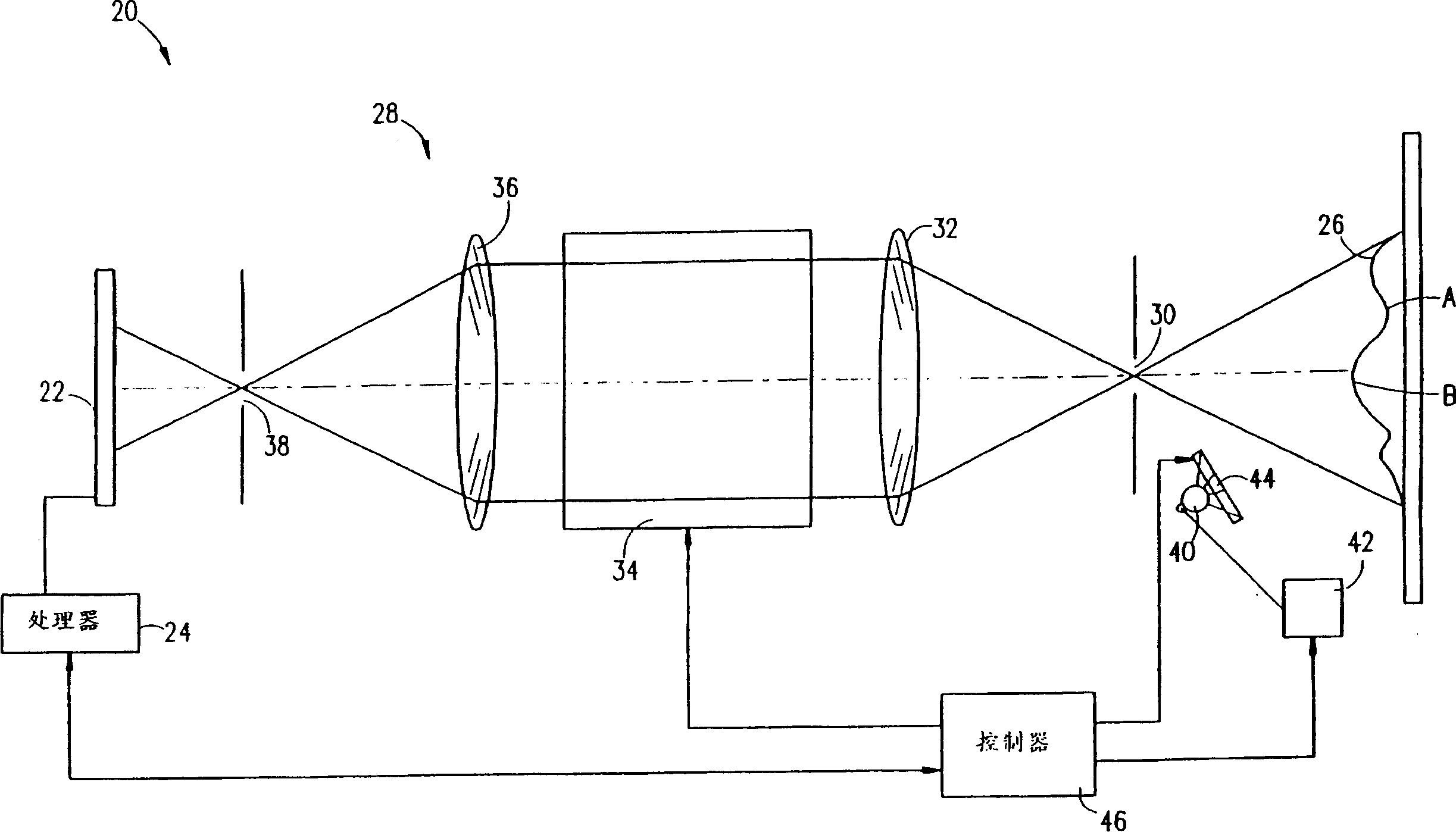
[0136] Now refer to figure 1 , which illustrates an optical distance measuring camera 20 according to a preferred embodiment of the present invention, as described in the above-mentioned second PCT application incorporated herein by reference. Camera 20 includes a detector array 22, preferably a CCD array, such as a KAF 0400 CCD array manufactured by Eastman Kodak, Rochester, New York, a HS 0512J CCD array manufactured by EG & G Reticon, Sunnyvale, California. Signals generated by CCD 22 are processed by video processor 24, which preferably produces a three-dimensional digital image, or three-dimensional video image, of scene 26 imaged by the camera, which indicates the distance to objects of interest, as discussed in more detail below.

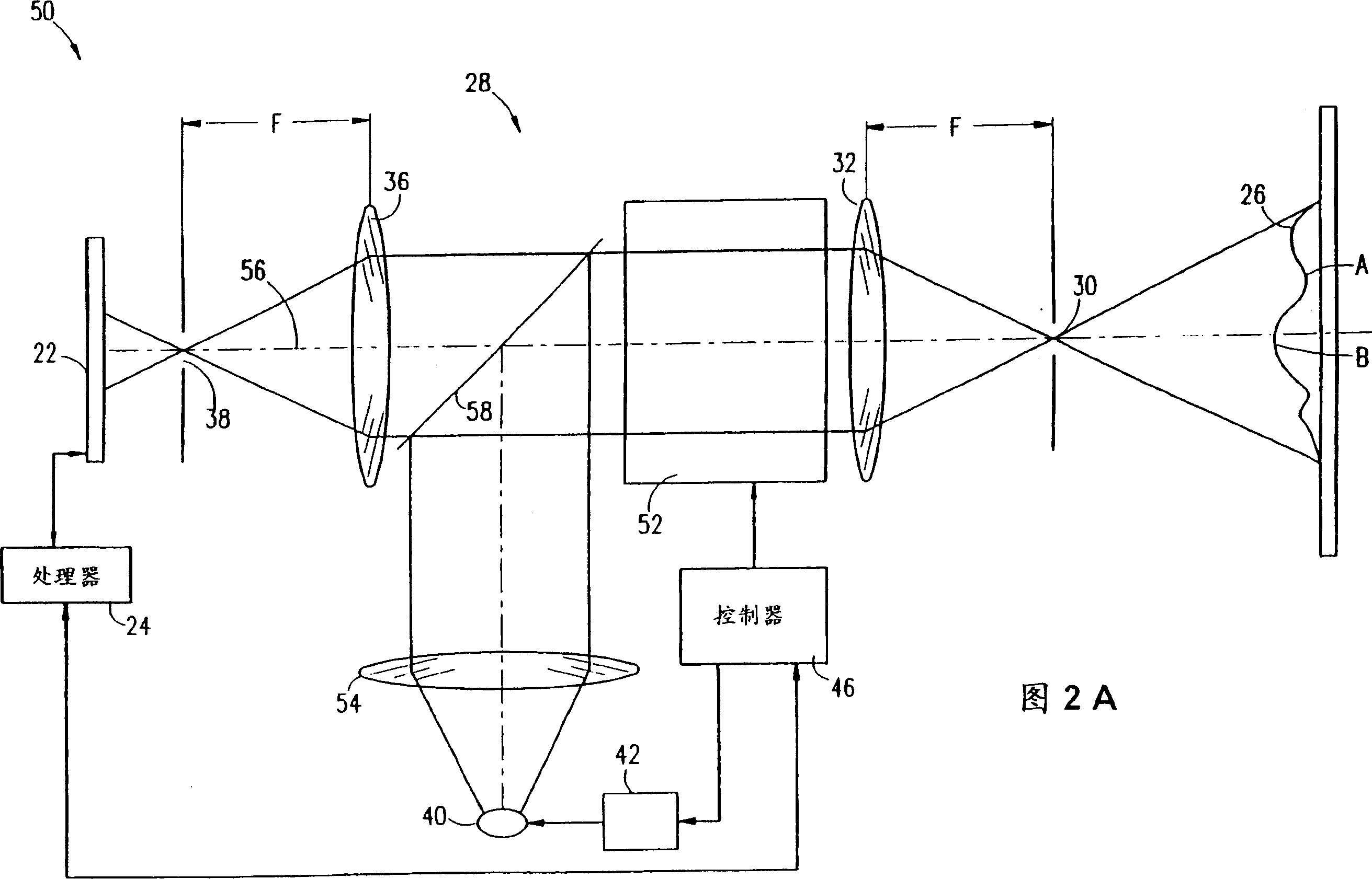
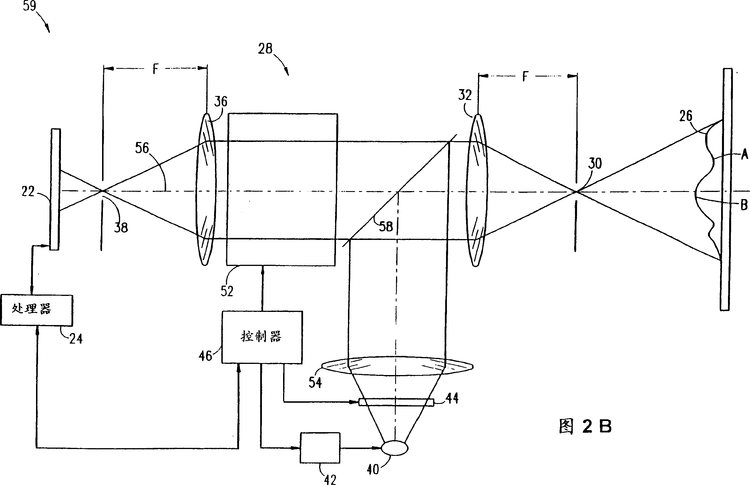
[0137] Camera 20 also includes an optical assembly 28 that modulates light received from scene 26 . Assembly 28 includes entrance aperture 30 , converging lens 32 , light modulator 3...


PUM


Abstract

Apparatus for creating an image indicating distances to objects in a scene, including a modulated source of radiation, having a first modulation function, which directs radiation toward a scene; a detector which detects radiation from the scene, modulated by a second modulation function, and generates, responsive to the detected modulated radiation, signals responsive to the distance to regions of the scene; and a processor which forms an image having an intensity value distribution indicative of the distance of objects from the apparatus, and a controller modulates at least one of the first and second modulation functions based on the intensity value distribution indicative formed by the processor.

Description

Field of invention: [0001] The present invention relates generally to systems for generating three-dimensional images, and more particularly to the ability to capture images of a scene and determine distances to objects and parts of the objects in the scene. Background of the invention: [0002] Various techniques are known for generating a three-dimensional image of a scene, ie an image including depth information or distance information. Typical methods are time-of-flight measurements, phase detection and triangulation. These techniques typically require, for example, scanning the image with a laser beam to acquire depth data point by point. However, in many applications it is desired to obtain the depth information or distance information of the entire image at the same time. [0003] US Patent 5,200,793, incorporated herein by reference, describes a distance sensing array camera comprising a light source and a CCD or other detector array. The photoelectric modulator m...

Claims


Application Information

Patent Timeline
Patent Type & Authority Applications(China)
IPC IPC(8): G01B11/00G01C3/06G01C11/02G01S7/48G01S7/481G01S7/51G01S15/89G01S17/02G01S17/08G01S17/18G01S17/88G01S17/894G01S17/931G01S17/933G02B7/32G03B35/00H04N13/04
CPCG01S17/08G01S17/89G01S15/89G01C11/025G01S7/4812G01S7/51G01S7/4802G01S7/4817G02B7/32G01S17/02G01S17/933G01S17/88G01S17/936G01S17/107G01S17/18G01S17/931G01S17/894
Inventor G·雅哈G·I·伊丹
Owner MAJKROSOFT INT KHLDGZ
Why Eureka
Try Eureka