Checking marker and electronic machine

A marking and electrical conduction technology, which is applied in the direction of assembling printed circuits, instruments, circuits, etc. with electrical components, can solve the problems of difficult to grasp the contact area between leads, unable to reduce the load of microscope inspection process, and unusable

Inactive Publication Date: 2003-09-03
TOHOKU PIONEER CORP
View PDF0 Cites 5 Cited by
  • Summary
  • Abstract
  • Description
  • Claims
  • Application Information

AI Technical Summary

Problems solved by technology

However, it is difficult to grasp the quality of the contact area between the leads by visual inspection, and the above-mentioned calibration marks for position adjustment can not be used because they are too fine to confirm the defective condition during visual inspection.
Therefore, in the visual inspection process, only defective products with obvious crimping defects can be excluded, and there is a problem that the load of the microscopic inspection process cannot be reduced.

Method used


Image

  • Checking marker and electronic machine
  • Checking marker and electronic machine
  • Checking marker and electronic machine

Examples


Embodiment Construction

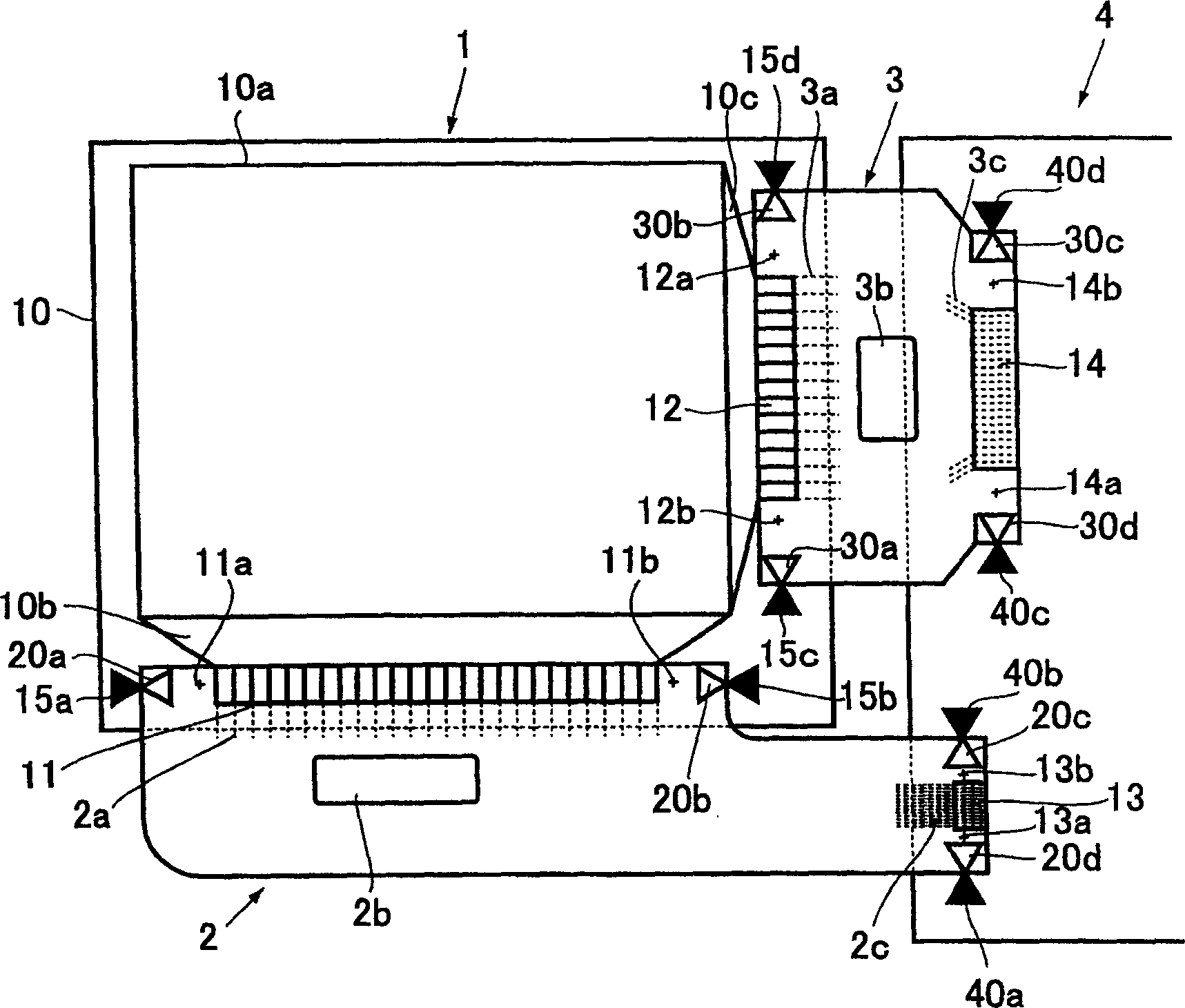
[0037] Embodiments of the present invention are described below in conjunction with figures. figure 1 A schematic diagram for revealing an embodiment of the present invention, revealing the assembly status of the electronic components of the display panel and the condition of markings for disposition inspection. In the figure, 1 is an organic EL display panel, 2 and 3 are TAB substrates, and 4 is a flexible substrate.

[0038] On the panel substrate 10 of the organic EL display panel 1, lead wires 10b, 10c used as signal lines are drawn out from the screen area 10a. , 3a are connected. The lead wires 2 b and 3 b are bonded to the driver ICs of the TAB substrates 2 and 3 .

[0039] The lead wires 2 c and 3 c of the TAB substrates 2 and 3 facing the flexible substrate 4 are connected to the connection areas 13 and 14 on the flexible substrate 4 by the connection wires on the flexible substrate 4 . Moreover, in the vicinity of the aforementioned connecting regions 11, 12, 13,...


PUM


Abstract

A test mark which is used in an inspection after a display panel, TAB tapes, and a flexible board have been connected together, and electronic device incorporating the same. Defective panels can be rejected with high accuracy in the simple inspection, thereby mitigating the burden on the microscopic inspection. At a predetermined distance from each of connection areas for connecting a panel substrate, TAB tapes, and a flexible board, there are provided test marks with at least one on each component. The electrical connection is tested between each pair of the test marks to thereby determine whether the interconnection is in a good state.

Description

technical field [0001] The present invention relates to an inspection mark provided on at least two mutually connected connection parts of a panel substrate, a TAB substrate, and a flexible substrate of a display panel for simply confirming a connection failure of the connection part and having an attached Electronic equipment such as display panels, TAB substrates, or flexible substrates with such inspection marks. Background technique [0002] With the popularization of mobile phones and personal digital assistants (PDAs), thin, light and compact display panels with strong display capabilities are in demand, and liquid crystal display panels and organic EL (electroluminescent) display panels are regarded as the ones that can meet their requirements. Display panels are used. [0003] In order to improve the display capability of such a display panel, in addition to improving the light control characteristics and light emission characteristics of each display element, the h...

Claims


Application Information

Patent Timeline
Patent Type & Authority Applications(China)
IPC IPC(8): G02F1/13G01R31/04G02F1/1345G09F9/00G09G3/00H01L21/60H05K1/02H05K1/14H05K3/36
CPCH05K2203/162H05K3/361G09G3/006H05K2201/09781H05K1/0268G01R31/04G01R31/66
Inventor 大峡秀隆
Owner TOHOKU PIONEER CORP
Why Eureka
Try Eureka