
Method for integrated covering single-pitch roof by using photocell board and large tile forming covering material

A photovoltaic panel and single-slope roof technology, which is applied in photovoltaic power generation, photovoltaic module support structure, roofing using tile/slate tile, etc. And other issues

Inactive Publication Date: 2003-09-24
GAMBALE
View PDF0 Cites 4 Cited by
  • Summary
  • Abstract
  • Description
  • Claims
  • Application Information

AI Technical Summary

Problems solved by technology

[0003] Prior Art The current conventional connection method destroys the impermeable performance of the roof due to the necessity of drilling holes
Also, these connection methods reduce the efficiency of the photovoltaic panels since there is no air circulation under the photovoltaic panels
In addition, the prior art methods do not have the integrity of the installation of the photovoltaic panels to the roof because the photovoltaic panels are installed with upsetting bars or stirrups fixed on the tiles, and sometimes the angle of the photovoltaic panels is different from that of the roof. Angle, which reduces the stability of the photovoltaic panels, which is especially important, in addition to spoiling the appearance of roof tiles, especially of high-quality buildings, photovoltaic panels are also affected by heavy air currents or large traction forces
[0004] Generally speaking, the current installation method has the following disadvantages: 1) there is no integrity or integrity between the roof tile surface and the photovoltaic panel; 2) the installation cost is high, and the maintenance cost is also high; 3) it is impossible to use The standard photovoltaic panel needs to provide a special photovoltaic panel for each different roof tile surface, so the cost is higher; 4) Since there is no air circulation, the photovoltaic panel is overheated, thereby reducing the working efficiency of the photovoltaic panel

Method used


Image

  • Method for integrated covering single-pitch roof by using photocell board and large tile forming covering material
  • Method for integrated covering single-pitch roof by using photocell board and large tile forming covering material
  • Method for integrated covering single-pitch roof by using photocell board and large tile forming covering material

Examples


Embodiment Construction

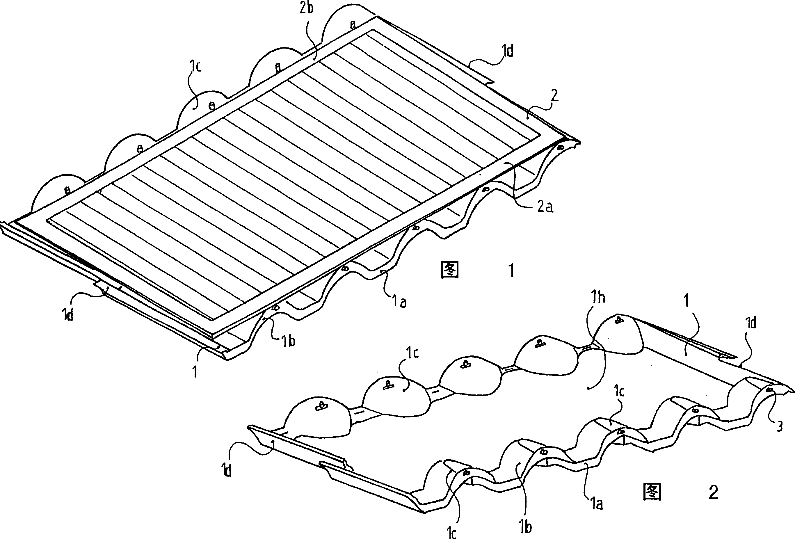
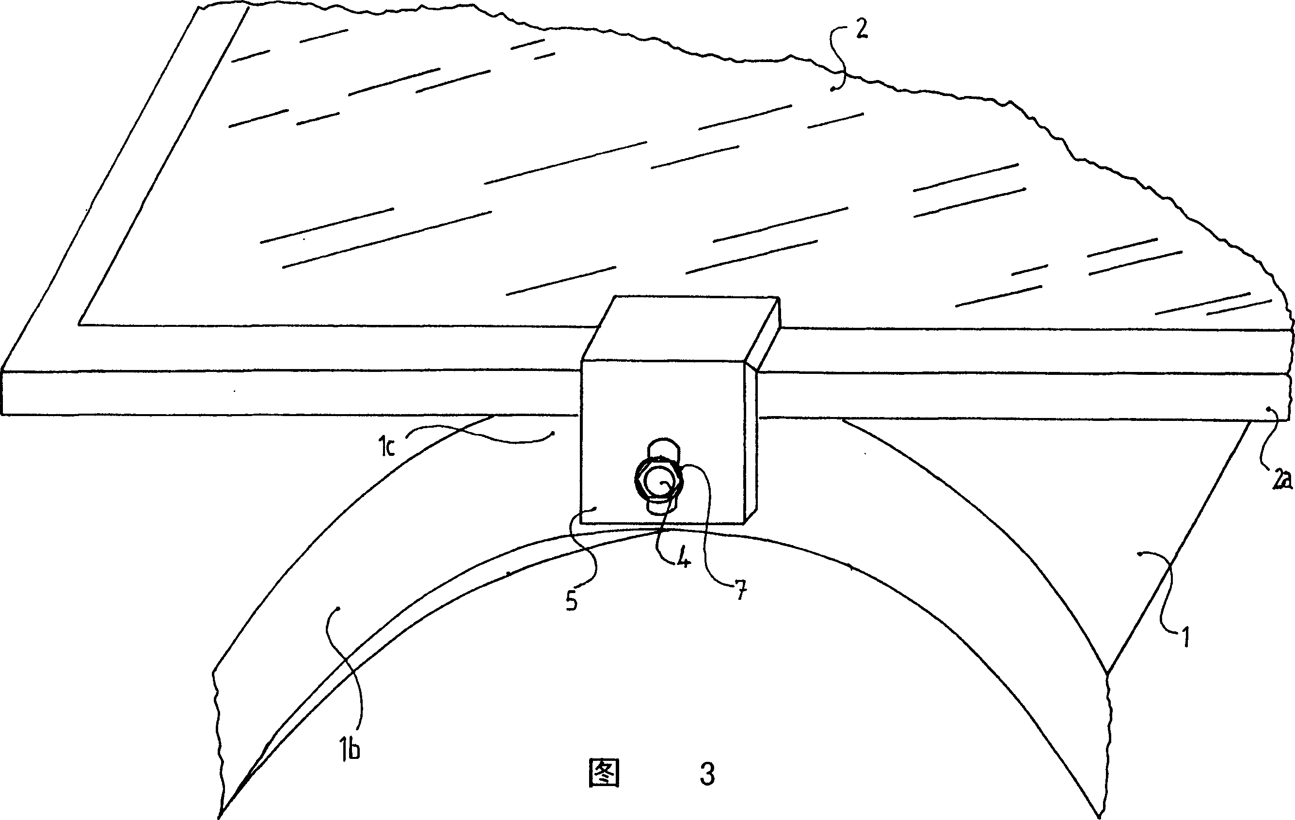
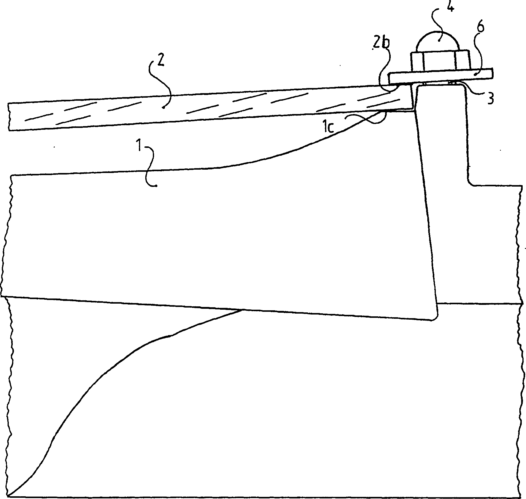
[0028]Please refer to shown in Fig. 1~4, the method of the present invention provides a kind of big big tile 1, and it is to make with the mould after the glass fiber reinforced concrete mixture is melted, then by the outer profile of big tile 1 in A photovoltaic panel 2 is defined thereon. The large tile 1 has an outer contour 1a, and the outer contour 1a is the same as the contour shape of a traditional tile, and its central part bends to a curved part 1b, and the curved part 1b goes up to a flat part 1c, on which the photovoltaic panel 2 rests . The side walls 1d of the large tiles can be combined (matched) with the conventional tiles that the large tiles 1 use for the rest of the roof if the contours of their connecting parts are continuous and complementary to each other. In addition, there is a fixing portion 1g on the underside of the outer side of the curved portion 1b for permanently fixing the photovoltaic cell-large tile to the supporting structure of the tile. Li...


PUM


Abstract

The present invention discloses a method for integrally-covering mono-pitched roof by using photoelectric cell plate to form covering large-tile. The described covering equipment and method includes a large tile no which a photoelectric cell plate is limited by means of its contour, the described large-tile has the external contour identical to that of traditional tile, the central portion of thelarge tile is bent toward bent portion, upper end surface of the bent portion has a flat portion, the photoelectric cell plate is placed on the flat portion, central portion of the large tile has a flat base bottom for maximally diffusing heat quantity so as to make photoelectric cell plate can work under the optimum condition. In order to firmly combine the photoelectric cell plate with large tile said invention adopts a kind of hexagonal screw bolt.

Description

field of invention [0001] The present invention relates to a new method for the tile sector of a roof where photovoltaic panels must be supported, and in particular to a method for using tiles of high section, i.e. with a height of more than two centimeters The sheet covers the fan-shaped part of the roof tile. The invention also relates to a large tile supporting the photovoltaic panel and forming the covering in the above covering method. Existing technologies increasingly use photovoltaic panels to generate non-polluting energy. The photovoltaic panel can be used to replace the traditional energy sources that pollute the environment and have high production costs and equipment maintenance costs. In countries with favorable climatic conditions, the use of photovoltaic panels is especially advantageous because they are used with high efficiency. Background of the invention [0002] The prior art method of installing photovoltaic panels is to use brackets or other support ...

Claims


Application Information

Patent Timeline
IPC IPC(8): E04D13/18H02S20/25
CPCY02B10/10Y02B10/20Y02E10/50
Inventor V·甘贝尔
Owner GAMBALE
Learn More