Determination of differential offset in radio device

A radio equipment, differential technology, applied in the field of measuring an offset value, which can solve problems such as environmental constraints and long time that cannot be considered in terms of component aging.

Inactive Publication Date: 2003-09-24
INTEL MOBILE COMM GMBH
View PDF0 Cites 4 Cited by
  • Summary
  • Abstract
  • Description
  • Claims
  • Application Information

AI Technical Summary

Problems solved by technology

However, the disadvantages of this process are the long time required for offset measurement and calibration, and in the production process, the calibration cannot take into account the actual situation of future component aging and environmental constraints.

Method used


Image

  • Determination of differential offset in radio device
  • Determination of differential offset in radio device
  • Determination of differential offset in radio device

Examples


Embodiment Construction

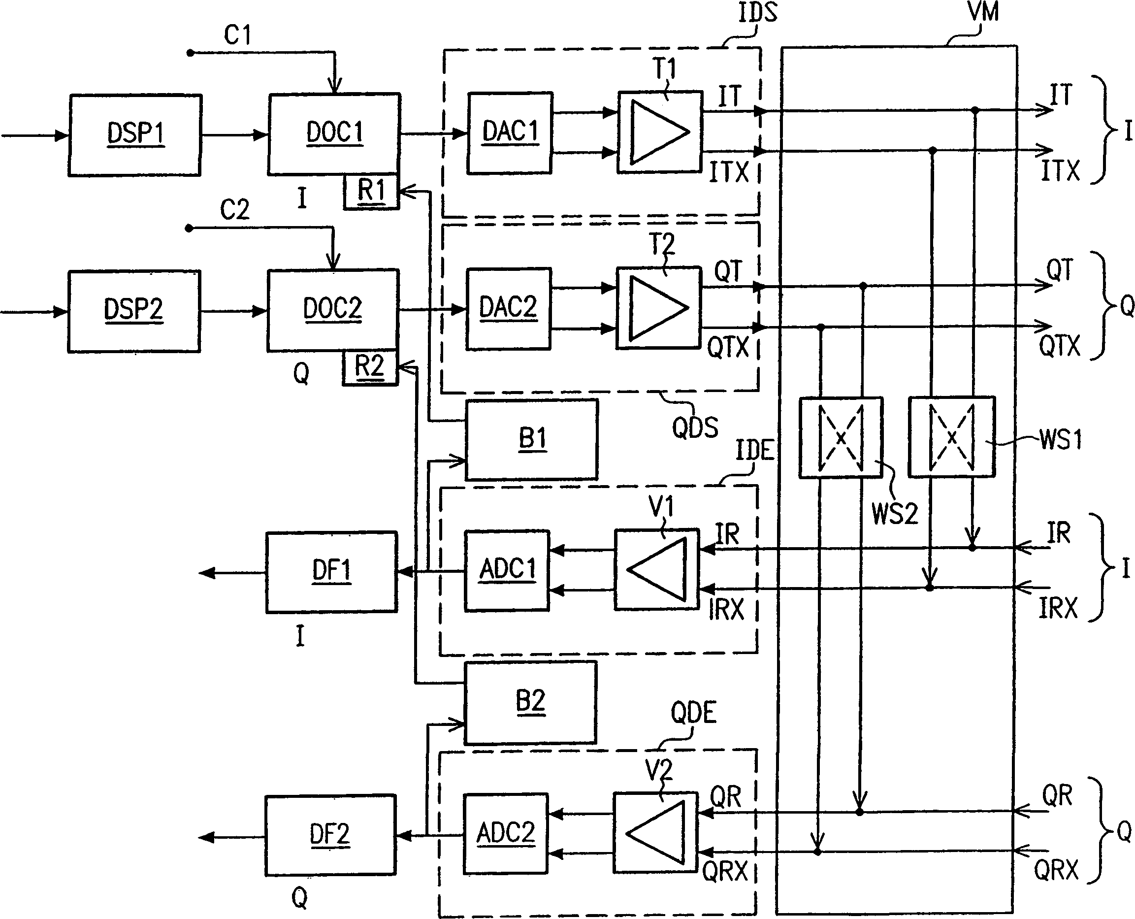
[0016] figure 1 Shows the structure of a baseband signal processing unit of a mobile radio device, such as a unit implemented in a baseband chip, in the form of a simplified block diagram. The transmission path in the signal processing unit includes an I (in-phase) branch, the first digital signal processor DSP1, the output of which is fed to the input of the first digital offset correction circuit DOC1. The data of DOC1 can be sent to the correction value register R1. An output of DOC1 can be fed to the input of the first digital-to-analog converter DAC1. DAC1 converts the incoming discrete-valued transmit signal (from the I branch) into two analog, differential transmit signals. The difference between the two signals in the differential transmit signal (regardless of the offset produced in DAC1) corresponds to the value of the signal at the input of DAC1.

[0017] Two analog, differential transmit signals are sent to the first driver T1. The first driver T1 performs sign...


PUM


Abstract

A method and apparatus for determining offset values ​​for offsets produced by differential transmit signal components (IDS, QDS) in use of radio equipment. In order to determine the above-mentioned offset values, the radio equipment has a signal processing unit (IDE, QDE) in the receiving part and also has a connection device (VM) for exchangeably connecting the differential transmit signal parts (IDS, QDS) The outputs are connected to the inputs of the differential receive signal parts (IDE, QDE).

Description

technical field [0001] The present invention relates to a method and a device for determining an offset value, which is an offset generated in a differential transmit signal component in a radio device. Background technique [0002] Signal processing in mobile radio devices (handy phones, mobile stations, etc.) includes signal processing in the baseband and signal processing in the radio frequency range. The corresponding two signal processing components (baseband and radio frequency components) are usually implemented by separate chips (baseband chip and radio frequency chip). The baseband chip is responsible for processing the digital modulation and D / A conversion of the signal to be transmitted, as well as the A / D conversion and demodulation of the received signal. The task of the radio frequency chip is to convert the analog baseband signal to be transmitted to the carrier frequency, and down-convert the received analog radio frequency signal to the baseband. [0003] ...

Claims


Application Information

Patent Timeline
Patent Type & Authority Applications(China)
IPC IPC(8): H04J3/00H04L25/02H04L25/06H04L25/08
CPCH04L25/085H04L27/0008H04L27/2017H04L27/2067
Inventor B·冈泽曼恩
Owner INTEL MOBILE COMM GMBH
Why Eureka
Try Eureka