Integrated lamp optical system and projector with the system

An illumination optical system and integral technology, applied in the field of integral illumination optical system, can solve the problem of high manufacturing cost

Inactive Publication Date: 2003-10-01
SEIKO EPSON CORP
View PDF0 Cites 5 Cited by
  • Summary
  • Abstract
  • Description
  • Claims
  • Application Information

AI Technical Summary

Problems solved by technology

For the manufacture of the lens array, since the advanced technology for the so-called "face sag" associated with the decrease in illuminance is required on the above-mentioned step portion, only a limited number of manufacturers can manufacture it, and there is a problem of high manufacturing cost.

Method used


Image

  • Integrated lamp optical system and projector with the system
  • Integrated lamp optical system and projector with the system
  • Integrated lamp optical system and projector with the system

Examples


Embodiment approach 1

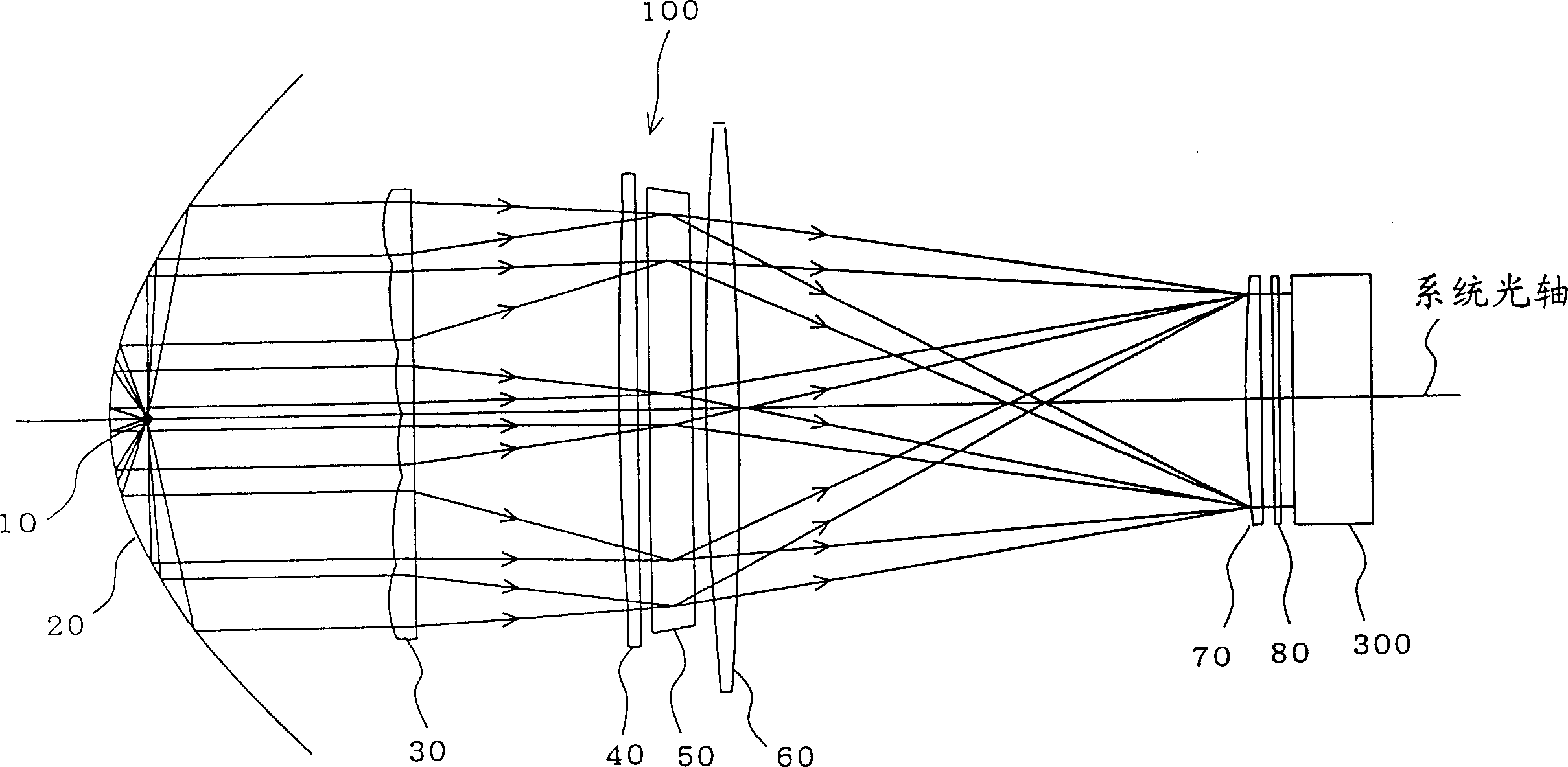
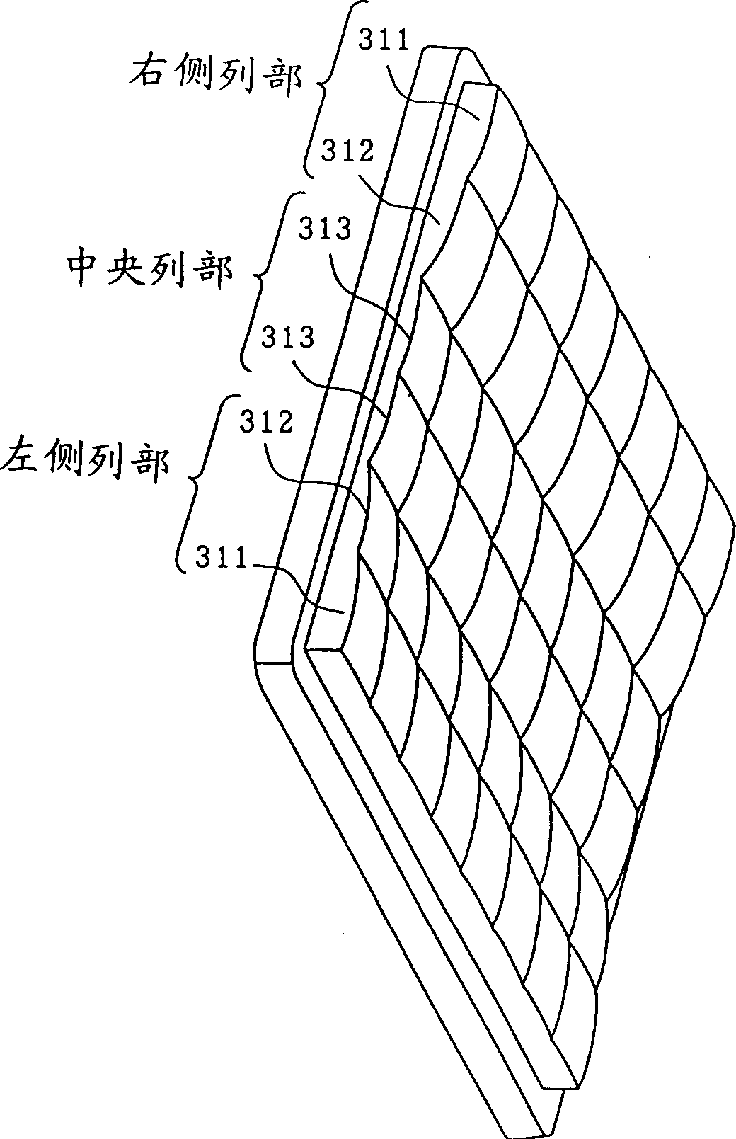
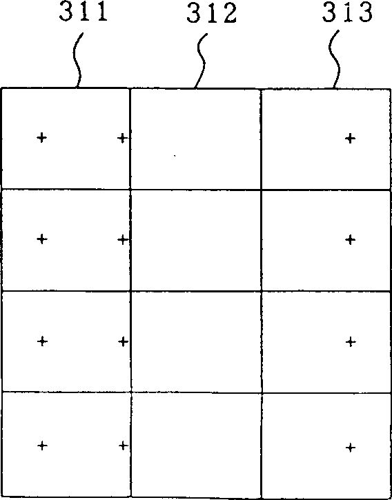
[0022] figure 1 It is an explanatory diagram of the structure and action of the integral illumination optical system according to the embodiment of the present invention, figure 2 is showing figure 1 A perspective view of the shape of the first lens array in, image 3 It is a front view showing the optical axis position of each lens unit constituting the first lens array, Figure 4 is showing figure 1 A perspective view of the shape of the second lens array in, Figure 5 is a front view showing the optical axis position of each lens unit constituting the second lens array, Image 6 is a front view of the light source image formed on the polarization conversion element 50 condensed by the first lens array, Figure 7 is showing figure 1 A perspective view of the structure of the polarization conversion element in Fig.

[0023] The integral illumination optical system 100 of the present embodiment, such as figure 1 As shown in , it includes: a lamp 10 as a light sou...

Embodiment approach 2

[0035] Next, an embodiment of a projector including the above-described integral illumination optical system 100 will be described. The projector of this embodiment, such as Figure 8 As shown in the optical system structure diagram, it is composed of the following parts: integral illumination optical system 100; color light separation optical system 200; liquid crystal panel 300 (300R, 300G, 300B); cross dichroic prism 400; and projection lens 500.

[0036] The color light separation optical system 200 includes first and second dichroic mirrors 201 and 202 , and separates light emitted from the illumination optical system 100 into three color lights of red, green, and blue. The first dichroic mirror 201 transmits the red light component of the light emitted from the illumination optical system 100 , and reflects blue light and green light components. The red light transmitted through the first dichroic mirror 201 is reflected by the reflection mirror 211 , passes through the...


PUM


Abstract

An integral illumination optical system with a first lens array and a second lens array, the first lens array is composed of three column groups, a left column group, a central column group and a right column group, so that the central column group The thickness of the lens unit is thinner than the thickness of the lens units of other column groups, so that the thickness of the lens units of the left column group and the right column group becomes thicker sequentially as the column becomes outer, and has the shape of the following form: The lens units of the side column group and the right column group make the incident light condense in the direction far away from the system optical axis of the integral illumination optical system, and the lens units of the central column group make the incident light converge in a direction close to the system light axis of the integral illumination optical system. Concentrate light in the direction of the axis.

Description

technical field [0001] The present invention relates to an integral illumination optical system that improves light utilization efficiency, and to a projector including the integral illumination optical system. Background technique [0002] In an illumination optical system using a polarization conversion element (or device), in order to utilize light as efficiently as possible, an integral illumination optical system is used. The integral illumination optical system is provided with a first lens array composed of a plurality of lens units having a rectangular shape similar to the display surface (or light incident surface) of the object to be illuminated, such as a liquid crystal panel, and the first lens array Each lens unit in the second lens array forms an image on the object to be illuminated. Therefore, the second lens array includes a plurality of lens units corresponding to the lens units of the first lens array. Moreover, recently, in order to further improve the ...

Claims


Application Information

Patent Timeline
Patent Type & Authority Applications(China)
IPC IPC(8): H04N5/74H04N9/31
CPCH04N5/7441H04N9/3102G03B21/14
Inventor 柳泽博隆
Owner SEIKO EPSON CORP
Why Eureka
Try Eureka