Belt transfer device and imaging equipment using the belt transfer device
An imaging device and belt conveying technology, which can be applied to equipment of electrical recording process applying charge pattern, electrical recording process applying charge pattern, transportation and packaging, etc., can solve problems such as cracking, complex structure, fluctuation, etc.
- Summary
- Abstract
- Description
- Claims
- Application Information
AI Technical Summary
Problems solved by technology
Method used
Image
Examples
Embodiment 1
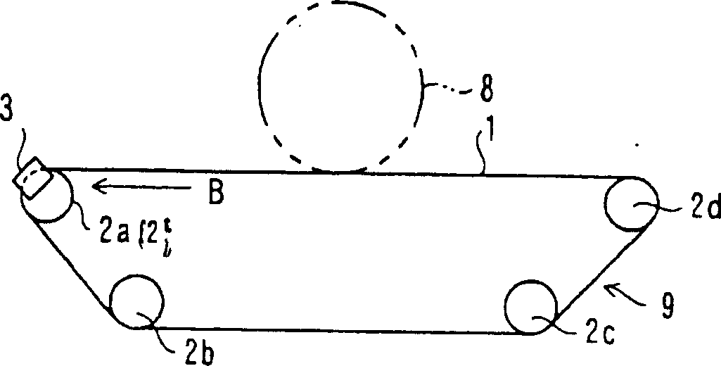
[0076] Figure 4 is a schematic diagram showing Embodiment 1 incorporating the image forming apparatus of the present invention.
[0077] In this figure, the image forming apparatus includes a photosensitive drum 10 and an intermediate transfer belt 20 that contacts the photosensitive drum 10 at a fixed area in a state where the intermediate transfer belt 20 extends along the shape of the photosensitive drum 10, and moves from The photosensitive drum 10 receives a toner image.
[0078] In this embodiment, the photosensitive drum 10 includes a photosensitive layer whose electrical resistance decreases under light. Set around the photosensitive drum 10: a charging unit 11 for charging the photosensitive drum 10; an exposure unit 12 for writing electrostatic latent images of various colors (in this embodiment: black, yellow, magenta, and cyan). to the charged photosensitive drum 10; the rotary developing unit 13 is used to develop the color latent image on the photosensitive dr...
Embodiment 2
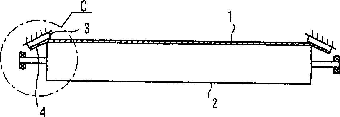
[0121] 6( a ) and FIG. 6( b ) show key parts (belt unit assembled with the intermediate transfer belt 20 ) of the belt conveying device of Embodiment 2. As shown in FIG.
[0122] In this figure, like Embodiment 1, the belt conveying device includes a guide member 50 close to the tension roller 22, but the structure of this guide member 50 is different from that of Embodiment 1.
[0123] The guide member 50 of this embodiment as shown in FIGS. 6( a ) and 6 ( b ) includes a guide shoe 51 provided at a portion opposite to the center portion of the bending region "m" of the tension roller 22 . The guide block 51 includes an arcuate guide surface 52 in contact with the belt end edge portion 20a.
[0124] Note that the intermediate transfer belt 20 passes the tension roller 22 in this embodiment. At the entrance and exit of the bending area "m" of the belt 1 on the tension roller 22, the tension pressure caused by the belt end edge portion 20a is large, and the belt end edge portio...
Embodiment 3
[0127] Figure 7 A key part of the belt conveying device (belt unit assembled with the intermediate transfer belt 20 ) of Embodiment 3 is shown.
[0128] In this figure, like Embodiments 1 and 2, the belt conveying device includes a guide member 50 close to the tension roller 22, but the structure of this guide member 50 is different from that of Embodiments 1 and 2.
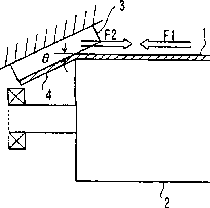
[0129] The guide member 50 of this embodiment rotates the guide roller 57 on the support bracket 56 . The belt end edge portion 20a protruding from one end of the tension roller 22 slides in contact with the rotating outer periphery of the guide roller 57 to adjust the bending.
[0130] In this embodiment, the sliding resistance value between the guide member 50 and the belt end edge portion 20a is extremely small. The frictional resistance associated with the guide member 50 does not prevent the intermediate transfer belt 20 from running.
[0131] As described above, according to the present invention, the g...
PUM
 Abstract
Description
Claims
Application Information
 - R&D
- Intellectual Property
- Life Sciences
- Materials
- Tech Scout
- Unparalleled Data Quality
- Higher Quality Content
- 60% Fewer Hallucinations
Browse by: Latest US Patents, China's latest patents, Technical Efficacy Thesaurus, Application Domain, Technology Topic, Popular Technical Reports.
© 2025 PatSnap. All rights reserved.Legal|Privacy policy|Modern Slavery Act Transparency Statement|Sitemap|About US| Contact US: help@patsnap.com


