Double-voice coil counter-connection coupling moving-coil loudspeaker

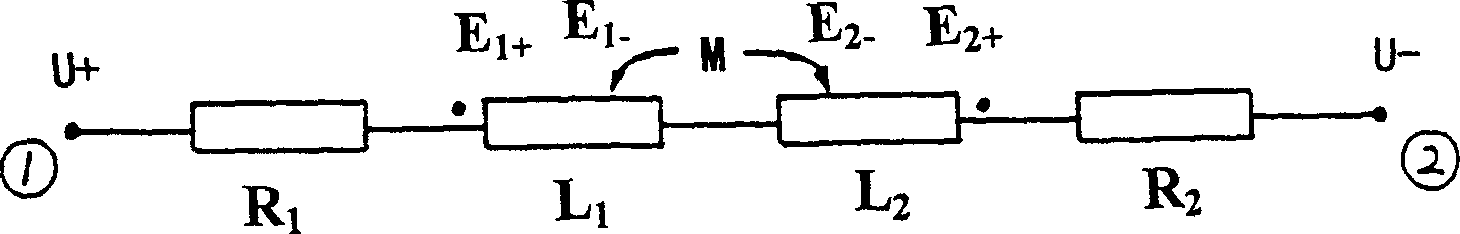
A dynamic speaker and dual voice coil technology, applied in the field of speakers, can solve problems such as inability to solve the inductance L and self-inductance voltage E, impedance characteristics that cannot be close to pure resistance, and speakers that cannot work

Inactive Publication Date: 2003-10-22
黄革雄
View PDF2 Cites 11 Cited by
  • Summary
  • Abstract
  • Description
  • Claims
  • Application Information

AI Technical Summary

Problems solved by technology

According to the magnetic field layout and the design structure of the double voice coil proposed by it, and according to the analysis that "the winding directions of the two voice coils should be opposite", the design has the following problems: 1. When the winding directions of the two voice coils are the same: Its effect is the same as that of ordinary dynamic speakers - it cannot solve the problems of inductance L and self-inductance voltage E
2. When the winding directions of the two voice coils are opposite: although the inductance L of the voice coil can be reduced, accordin

Method used


Image

  • Double-voice coil counter-connection coupling moving-coil loudspeaker
  • Double-voice coil counter-connection coupling moving-coil loudspeaker
  • Double-voice coil counter-connection coupling moving-coil loudspeaker

Examples


Embodiment Construction

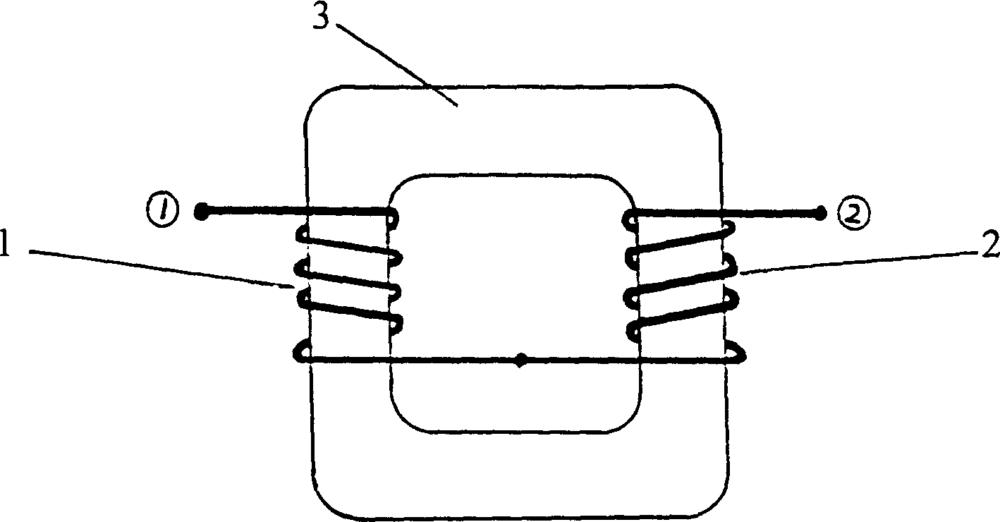
[0062] Several specific embodiments that can effectively implement the present invention are given in the accompanying drawings of the description. In practical applications, the shape of the double voice coil and the shape of the closed mutual inductance coupling magnetic conduction loop can be designed into various variations according to the basic principles of the present invention. Figure 4 in the accompanying drawings, Figure 5 , Figure 6, Figure 7, and Figure 8 are designed mainly for mid-bass speakers, Figure 9 Figure 10 Figure 11 Figure 12 Figure 13 Figure 14 Designed primarily for mid- and high-range speakers. The specific implementation manners of the present invention will be further described in conjunction with the accompanying drawings. In order not to affect the cleanliness of the drawings, the two external connection terminals of the speaker, the connection lines between the two voice coils and the connection lines between the two voice coils and...


PUM


Abstract

A loud speaker comprises voice coil, magnet steel, voice basin, basin frame, positioning fold ring, magnetic conductor and line connecting terminal. It applies two voice coils as they are independentand in structure of two boneframe being wound separately, are connected in reversing series and placed at magnetic field in the samd direction and the same strength as well as they are erected in mode of parallel or coaxial and equipped with closed mutual inductive coupled and magnetic conductive loop which is passing through two coils.

Description

technical field [0001] The present invention relates to a loudspeaker, more specifically, it relates to a novel moving coil loudspeaker. Background technique [0002] Dynamic speakers are the most widely used speakers today, especially in high-fidelity audio. Existing traditional moving coil loudspeakers have only one voice coil (coil) in structure, and are placed in a magnetic field formed by magnetic steel and magnetically permeable materials. When the voice coil is fed with the audio current output by the amplifier, the voice coil will be moved by the magnetic field where it is located, pushing the connected sound cone to drive the air in the sound cone to vibrate, thus producing sound. As a high-fidelity audio system, every link is very important, from front-stage signal amplification, post-stage power amplification to speaker playback. The ideal load for the post-stage power amplifier should be a purely resistive device—that is, a device with a linear volt-ampere rela...

Claims


Application Information

Patent Timeline
IPC IPC(8): H04R9/06H04S1/00
Inventor 黄革雄
Owner 黄革雄
Why Eureka
Try Eureka