Eureka AIR delivers breakthrough ideas for toughest innovation challenges, trusted by R&D personnel around the world.

Low-profile dual-polarization strong-coupling ultra-wideband full-wing conformal dipole phased-array antenna

A phased array antenna and dual-polarization technology, which is applied in the field of wireless communication and antenna engineering technology, can solve the problems that the antenna beam cannot cover the half-space of the wing, the overall gain is low, and the application limit is limited, so as to enhance the overall performance and flexibility performance, large scanning angle, and the effect of reducing coupling

Pending Publication Date: 2022-05-31
UNIV OF ELECTRONIC SCI & TECH OF CHINA
View PDF5 Cites 0 Cited by
  • Summary
  • Abstract
  • Description
  • Claims
  • Application Information

AI Technical Summary

Problems solved by technology

However, only two radiating elements are arranged in one period of the antenna, the overall gain is low, and only single-line polarization radiation can be realized, so the application occasions are greatly limited
[0007] In the Chinese patent with the patent number CN112038753A, the inventor proposed a thin wing conformal dual-polarization strong coupling ultra-broadband dipole phased array, the antenna array uses a cross-shaped dipole radiation unit to achieve Dual polarization is adopted, but the radiating elements of this antenna are only distributed on one side of the wing. In practical applications, the antenna beam cannot cover the half space where the other side of the wing is located, and there are certain limitations.

Method used


Image

  • Low-profile dual-polarization strong-coupling ultra-wideband full-wing conformal dipole phased-array antenna
  • Low-profile dual-polarization strong-coupling ultra-wideband full-wing conformal dipole phased-array antenna
  • Low-profile dual-polarization strong-coupling ultra-wideband full-wing conformal dipole phased-array antenna

Examples


Embodiment Construction

[0027] In order to make the purpose, technical solution and advantages of the present invention clearer, the present invention will be further described in detail below in conjunction with the implementation methods and accompanying drawings.

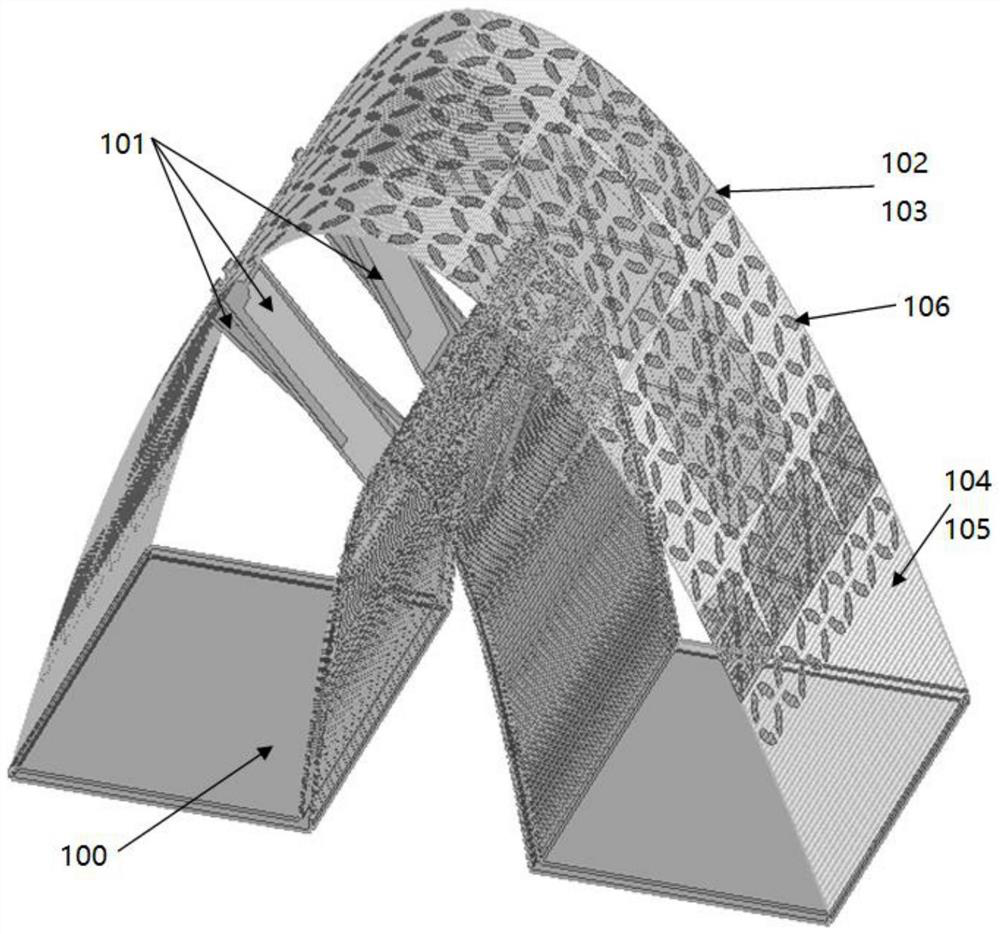
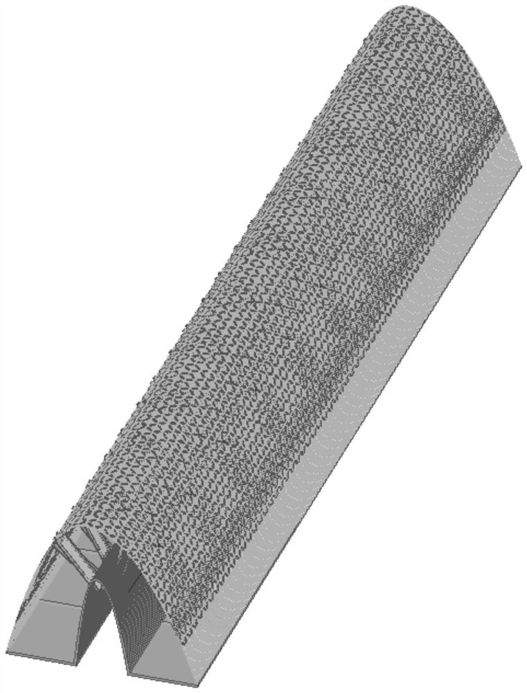
[0028] The strong-coupling ultra-wide bandwidth angular scanning low-profile full-wing conformal dipole phased array antenna of this embodiment adopts a 1×10 linear array form, such as figure 2 shown. Its basic antenna elements such as figure 1 shown. The uppermost layer is two layers of light and thin dielectric substrates 104 and 105, which are bent into a parabolic shape. The upper dielectric substrate 105 is printed with double-opened metal resonant rings. The upper surface of the lower dielectric substrate 104 is printed with dual-polarized triangular dipole radiating units 102 placed orthogonally, and directly below the dipole is a triangular metal parasitic patch 103 . The lowest layer of aluminum metal floor 100 is speciall...


PUM


Abstract

The invention discloses a low-profile dual-polarization strong-coupling ultra-wideband full-wing conformal dipole phased-array antenna, which comprises an upper dielectric substrate and a lower dielectric substrate which are light and thin and are easy to bend, and a crisscross triangular dipole radiation unit printed on the lower dielectric substrate, the triangular metal parasitic patch is printed on the back surface of the dipole radiation unit; the double-opening metal resonance rings are printed on the lower-layer dielectric substrate and are distributed periodically, the middle part of the aluminum metal floor is bent into a paraboloid shape, and the antenna feed balun is directly inserted between the dipole antenna radiation unit and the floor; four radiation units are arranged in each polarization mode in a parabola surface with 0.33 low-frequency wavelength in length, 0.16 low-frequency wavelength in width and 0.24-time high low-frequency wavelength as a period, the total number of the radiation units is eight, and high gain and an ideal directional diagram are achieved in five frequency multiplications.

Description

technical field [0001] The invention belongs to the fields of antenna engineering technology and wireless communication technology, and in particular relates to an ultra-broadband low-profile wide-angle scanning full-wing conformal phased array antenna based on strong mutual coupling effect. Background technique [0002] With the development of modern military technology, the design requirements of radar electronic systems are becoming more and more complex and diverse, such as fast and changeable beam pointing, high-precision beam scanning capabilities, etc. Under this premise, the traditional mechanical scanning phased array obviously cannot meet the requirement of fast switching of beam pointing, and the phased array antenna that realizes the change of beam pointing by changing the feeding phase of each antenna unit is the realization of radar detection technology. key part of . Modern military systems often require phased array antennas to achieve long-distance high-res...

Claims


Application Information

Patent Timeline
IPC IPC(8): H01Q1/48H01Q1/38H01Q1/50H01Q3/32H01Q21/24
CPCH01Q1/48H01Q1/50H01Q1/38H01Q21/24H01Q3/32H01Q21/0006
Inventor 杨仕文张昊天杨锋黄明屈世伟陈益凯胡俊
Owner UNIV OF ELECTRONIC SCI & TECH OF CHINA
Why Eureka
Eureka Blog
Learn More