Snow melting device using geothermal energy

A geothermal and heat pump technology, applied in the field of snow melting devices

Inactive Publication Date: 2003-10-29
ミサワ環境技術
View PDF0 Cites 12 Cited by
  • Summary
  • Abstract
  • Description
  • Claims
  • Application Information

AI Technical Summary

Problems solved by technology

Therefore, it provides a snow melting device that can melt snow without causing problems such as subside

Method used


Image

  • Snow melting device using geothermal energy
  • Snow melting device using geothermal energy
  • Snow melting device using geothermal energy

Examples


Embodiment Construction

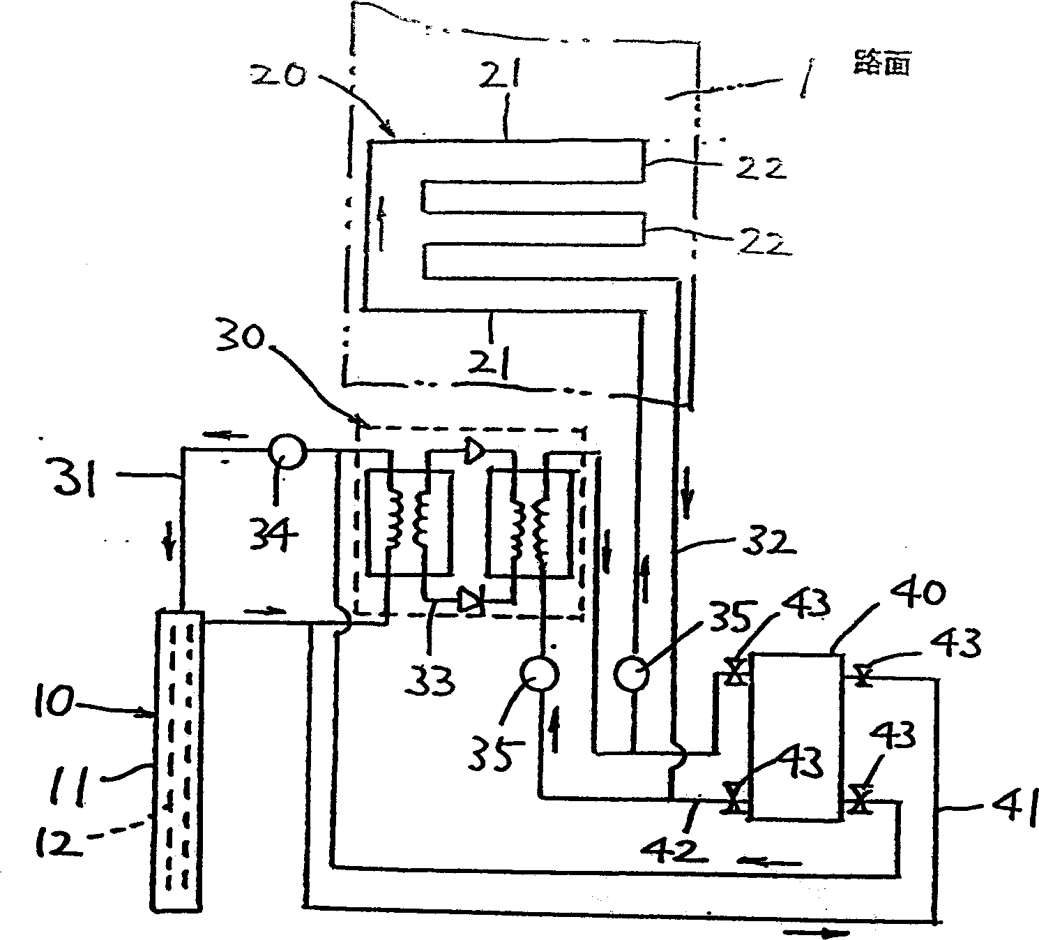
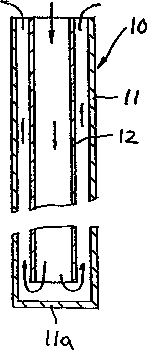
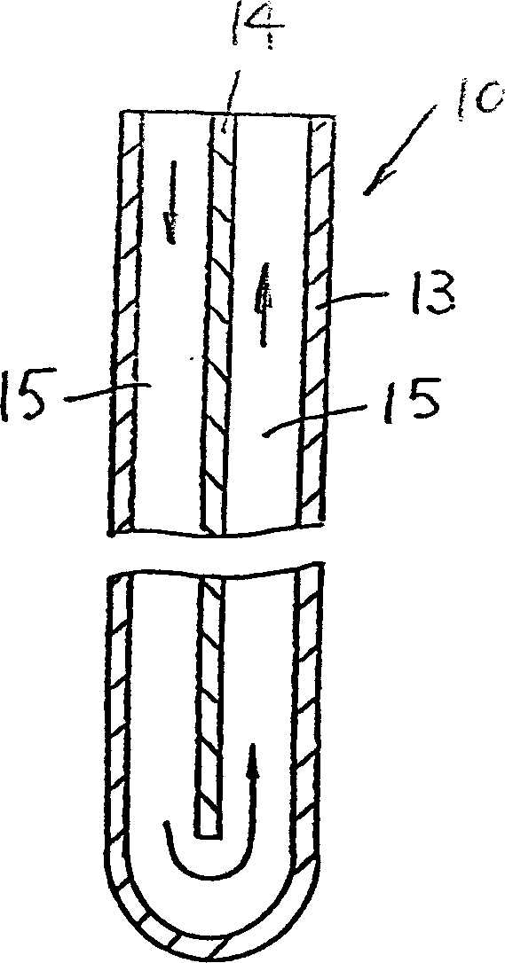
[0007] The present invention utilizes the implementation form of geothermal snow melting device, as figure 1 and 2 shown. The snow melting device is composed of several main parts of a heat exchanger 10 , a heat release pipe 20 , a heat pump 30 and a heat storage tank 40 .

[0008] The heat exchanger 10 is composed of a concentric inner cylinder 12 inside an outer cylinder 11 with a bottom wall 11a, buried vertically to a depth of 150m underground, and collects geothermal heat through the first liquid medium (antifreeze) circulating therein. The first liquid medium flows down from the upper end of the inner cylinder 12, turns back into the space between the outer cylinder 11 and the inner cylinder 12 at the lower end, and performs geothermal heat exchange during the rising process to complete geothermal collection.

[0009] The heat radiation pipe 20 is composed of a long side 21 and a short side 22 , and is laid in a hairpin shape right under the road surface 1 . There is ...


PUM


Abstract

A snow-melting device capable of melting snow is provided on the premise that problems such as subsidence of the foundation, icing on the road surface, and water splashing are not induced by using effective, clean, and cheap energy. The outer cylinder 11 is concentrically inserted into the inner cylinder 12 and buried vertically in the ground, in which the first liquid medium is circulated, a heat exchanger 10 for collecting geothermal heat, and buried directly below the road surface 1 in a hairpin shape, wherein The second liquid medium circulates, the heat release pipe 20 that melts the snow on the road surface 1 by releasing heat, the heat pump 30 that heats up the heat of the first liquid medium and then transfers it to the second liquid medium, and the heat storage tank 40 that stores heat. And the heat exchanger 10 and the heat pump 30 are connected through a first loop 31 , while the heat pump 30 and the heat release pipe 20 are connected through a second loop 32 . The first loop 31 and the heat storage tank 40 are connected through a first communication path 41 , while the second loop 32 and the heat storage tank 40 are connected through a second communication path 42 .

Description

technical field [0001] The invention relates to a snow melting device which utilizes collected geothermal heat to melt snow on roads, tracks of lines and the like. Background technique [0002] In the past, in order to melt snow on roads and railway tracks, the method of pumping groundwater from wells and spraying it on the road surface was adopted. Such a method has the advantages of not polluting the atmosphere and low operating costs because it utilizes the groundwater drawn up as an energy source that does not cause pollution. Contents of the invention [0003] However, using the original technology, because a large amount of groundwater must be drawn, it is easy to cause major problems such as foundation subsidence. Moreover, the water sprinkled on the road surface will splash on passing vehicles and pedestrians, and if the outside temperature is low, it will also cause the road surface to freeze, becoming a hidden danger of inducing traffic accidents. [0004] In o...

Claims


Application Information

Patent Timeline
IPC IPC(8): E01H5/10E01C11/26F24J3/08F25B30/02
CPCY02E10/10
Inventor 洲泽昭已
Owner ミサワ環境技術
Why Eureka
Try Eureka