Coating forming method, apparatus and device, method for mfg. device and electronic apparatus

一种涂层、设备的技术,应用在涂层形成设备领域,能够解决设备质量下降等问题,达到好连续性的效果

Inactive Publication Date: 2003-10-29
SEIKO EPSON CORP
View PDF0 Cites 3 Cited by
  • Summary
  • Abstract
  • Description
  • Claims
  • Application Information

AI Technical Summary

Problems solved by technology

Therefore, it will be related to the possible degradation of equipment quality

Method used


Image

  • Coating forming method, apparatus and device, method for mfg. device and electronic apparatus
  • Coating forming method, apparatus and device, method for mfg. device and electronic apparatus
  • Coating forming method, apparatus and device, method for mfg. device and electronic apparatus

Examples


Embodiment Construction

[0039] The present invention will be described in detail below.

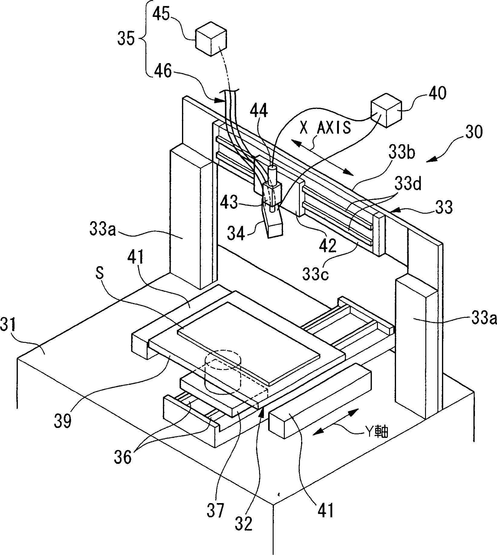
[0040] figure 1 An example of a coating forming apparatus according to the present invention is shown. figure 1Reference numeral 30 denotes a coating forming apparatus. The coating forming apparatus 30 is configured with a base 31, a motherboard operating part 32, a head moving part 33, a liquid drop discharge head 34, a liquid supply part 35, a control part 40, and the like. Both the motherboard operating part 32 and the head moving part 33 are mounted on the base 31 . The motherboard handling part 32 is mounted on the base 31 . The motherboard operating unit 32 is equipped with a guide rail 36 arranged along the Y-axis direction. The motherboard operating part 32 can move the slider 37 along the guide rail 36 by, for example, a linear motor (not shown in the figure).

[0041] The platform 39 is fixed on the slider 37 . The motherboard S is placed on the platform 39 and kept at a predetermined position. ...


PUM


Abstract

A large number of unit areas (bits) B are provided on the motherboard (S). Droplets made of a certain liquid composition are ejected from the droplet ejection head (34) to the unit area B to form a coating layer on the mother substrate (S). A first group of nozzles Na consisting of N nozzles in the ejection head (34) forms a first pattern. The second group of nozzles Nb different from the first group of nozzles Na forms a second pattern. In doing so, when patterns having different characteristics are formed on the reference plate, it is possible to maintain a stable ejection operation and form patterns with better precision using this droplet ejection device.

Description

technical field [0001] The present invention relates to a coating layer forming method and a coating layer forming apparatus using a droplet discharge device, and to the resulting device and manufacturing method and an electronic device. Background technique [0002] Conventionally, the fabrication of precise wiring patterns for semiconductor integrated circuits is usually carried out by photo-lithography. Recently, several methods using certain droplet ejection methods have been published. According to this method, a liquid portion containing a pattern-forming composition is ejected from a liquid drop discharge head to a motherboard; thus, a wiring pattern is formed by arranging the pattern-forming composition on the pattern-forming surface. It is understood that this technique would be very effective for the production of multiple products in small batches (see Japanese Unexamined Patent Application First Publication No. Hei 11-274671, and see Japanese Unexamined Patent A...

Claims


Application Information

Patent Timeline
Patent Type & Authority Applications(China)
IPC IPC(8): B41J2/01B05C5/00B05D1/26B05D5/12B41J2/21B41J2/51B41J3/28H01J9/02H01L21/00H01L21/288H01L21/768H05K3/12
CPCB41J2/2132B41J3/28H01L21/288H01L21/6715H01L21/76838H05K3/125B41J25/003Y10T428/24802B41J29/00
Inventor 小山实平井利充
Owner SEIKO EPSON CORP
Why Eureka
Try Eureka