Transmission method for magnetic resonance signal and relevant receiving device and magnetic resonance apparatus

A magnetic resonance signal and receiving device technology, applied in magnetic resonance measurement, measuring devices, measuring magnetic variables, etc., can solve problems such as limiting the friendliness of operation and limiting the reliability of surface coil signal transmission

Inactive Publication Date: 2003-11-12
SIEMENS AG
View PDF1 Cites 7 Cited by
  • Summary
  • Abstract
  • Description
  • Claims
  • Application Information

AI Technical Summary

Problems solved by technology

However, this cable and the required plug contacts limit the operator-friendliness and also the reliability of the surface coil and the corresponding signal transmission

Method used


Image

  • Transmission method for magnetic resonance signal and relevant receiving device and magnetic resonance apparatus
  • Transmission method for magnetic resonance signal and relevant receiving device and magnetic resonance apparatus
  • Transmission method for magnetic resonance signal and relevant receiving device and magnetic resonance apparatus

Examples


Embodiment Construction

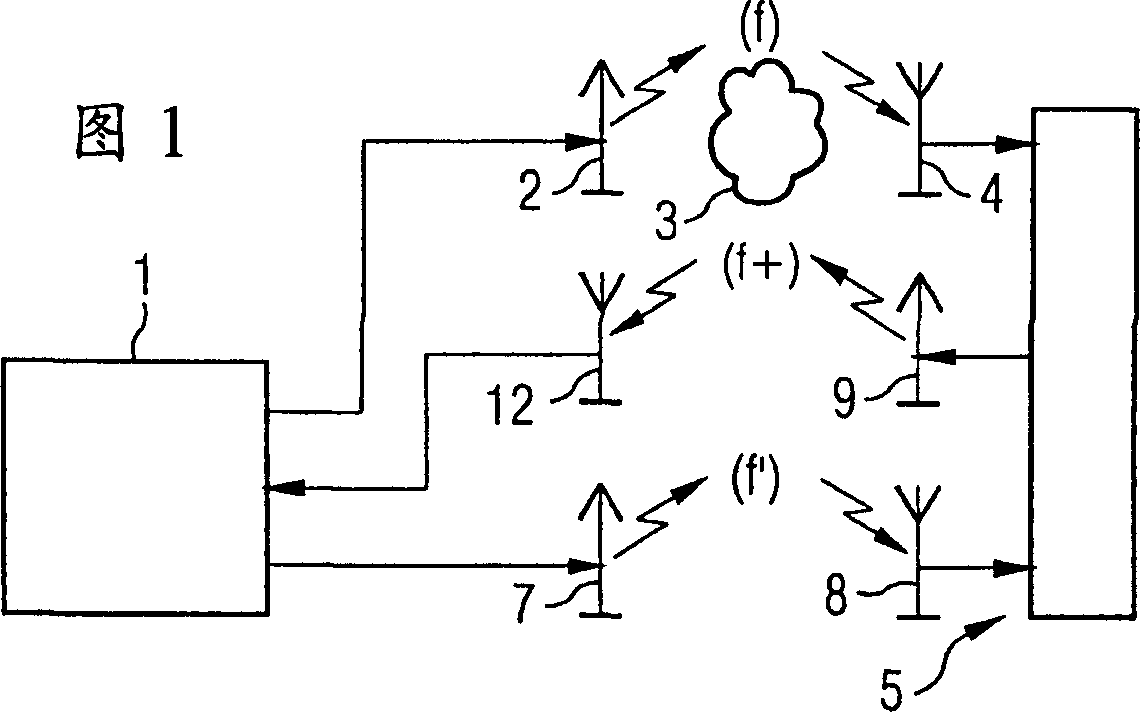
[0034] According to Figure 1 and figure 2 , the magnetic resonance system has a control and processing device 1 . Among other things, the control and processing device 1 controls the magnetic resonance transmission antenna 2 in such a way that it transmits magnetic resonance excitation signals at a magnetic resonance frequency f. Based on this magnetic resonance excitation signal, the examination object 3 (for example a person) is excited to magnetic resonance.

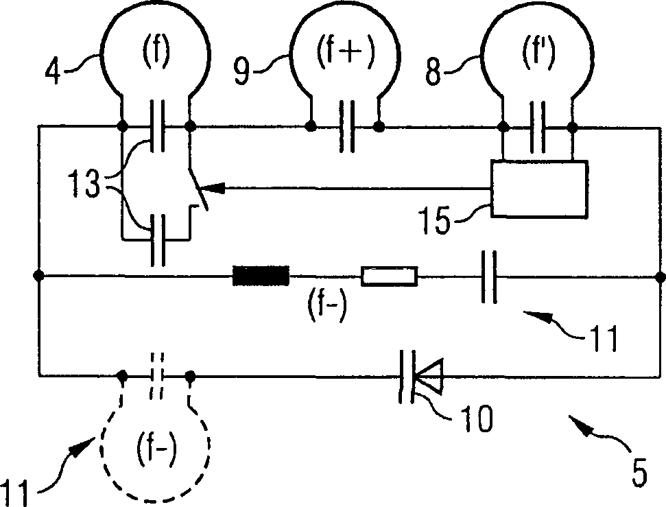
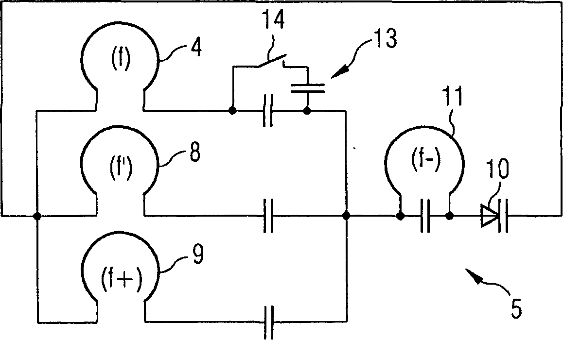
[0035] After excitation of the examination object 3 to magnetic resonance, magnetic resonance signals are received by the magnetic resonance reception antenna 4 of the reception device 5 . The received magnetic resonance signals likewise have a magnetic resonance frequency f. The received magnetic resonance signals are transmitted unaltered, in particular unamplified, by the magnetic resonance reception antenna 4 to the nonlinear reactance 10 .

[0036] The magnetic resonance antenna also has an auxiliary transmitt...


PUM


Abstract

A magnetic resonance signal from a magnetic resonance receiver antenna (4) and an auxiliary energy fed from an auxiliary receiver antenna (8) is transfered to a non-linear reactance (10). The auxiliary energy is transmitted by an auxiliary transmitter antenna (7). The non-linear reactance (10) mixes the auxiliary energy and magnetic resonance signal to form a mixed signal with a given frequency (f+), and transfers it to a mixed signal transmitter antenna. The mixed signal transmitter antenna emits the mixed signal with a given frequency (f+). A mixed signal receiver antenna (12) receives the mixed signal, and transmits it to a processing device (1).

Description

technical field [0001] The invention relates to a transmission method for transmitting magnetic resonance signals from a magnetic resonance reception antenna to a processing device. The invention also relates to a receiving device for magnetic resonance signals, which is suitable for carrying out the method, and a corresponding magnetic resonance system. Background technique [0002] Due to the achievable signal-to-noise ratio, it is advantageous for magnetic resonance systems to use so-called local coils or surface coils. Such coils are generally connected to the processing unit by cables. However, this cable and the required plug contacts limit the ease of use and also the reliability of the surface coil and the corresponding signal transmission. [0003] It is also known to convert received magnetic resonance signals into another frequency and to transmit them wirelessly to a processing device. For this purpose, in the prior art, an auxiliary energy source (for example...

Claims


Application Information

Patent Timeline
Patent Type & Authority Applications(China)
IPC IPC(8): G01R33/36
CPCG01R33/3692H03F7/04
Inventor 奥利弗·海德马库斯·维斯特
Owner SIEMENS AG
Why Eureka
Try Eureka