Piano keyboard acting photoelectronic digital detector

A digital detection and keyboard technology, applied in stringed instruments, instruments, etc., can solve the problems of inability to fully reflect keyboard actions, difficult to digitally reflect detection results, and poor detection accuracy, and achieve stable and reliable performance, sensitive reflection, and fewer conversion links.

Inactive Publication Date: 2003-11-19
孙玮
View PDF0 Cites 6 Cited by
  • Summary
  • Abstract
  • Description
  • Claims
  • Application Information

AI Technical Summary

Problems solved by technology

The former converts the action of the keyboard into electrical signals during the playing process through the electromagnetic induction elements that are relatively fixed to the piano frame and the keys respectively, so as to realize the detection of the keyboard action. The disadvantage is that the cost is high and it is difficult to digitally reflect the detection results; The on-off control of the two reeds, which are relatively fixed to the piano frame and the keys, respectively, during the playing process, sends out corresponding electrical signals to realize the detection of keyboard actions. The disadvantage is that the detection accuracy is poor, and it cannot fully reflect the actions of the keyboard.

Method used


Image

  • Piano keyboard acting photoelectronic digital detector
  • Piano keyboard acting photoelectronic digital detector
  • Piano keyboard acting photoelectronic digital detector

Examples


Embodiment 1

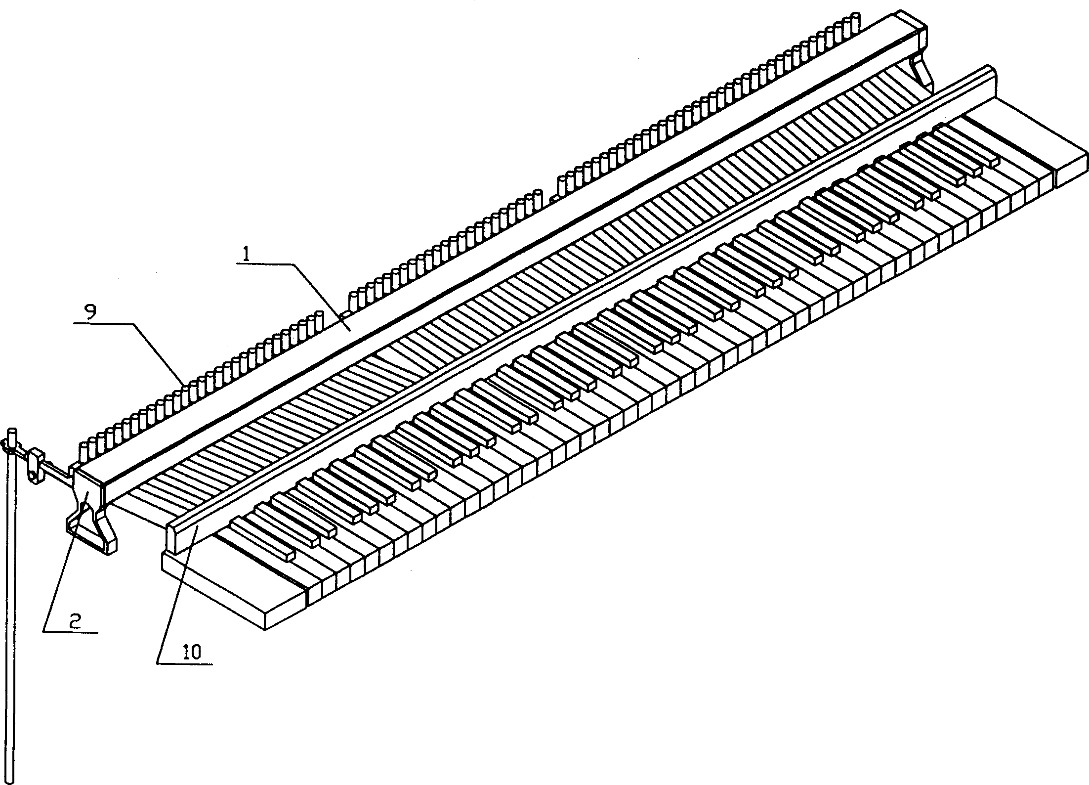
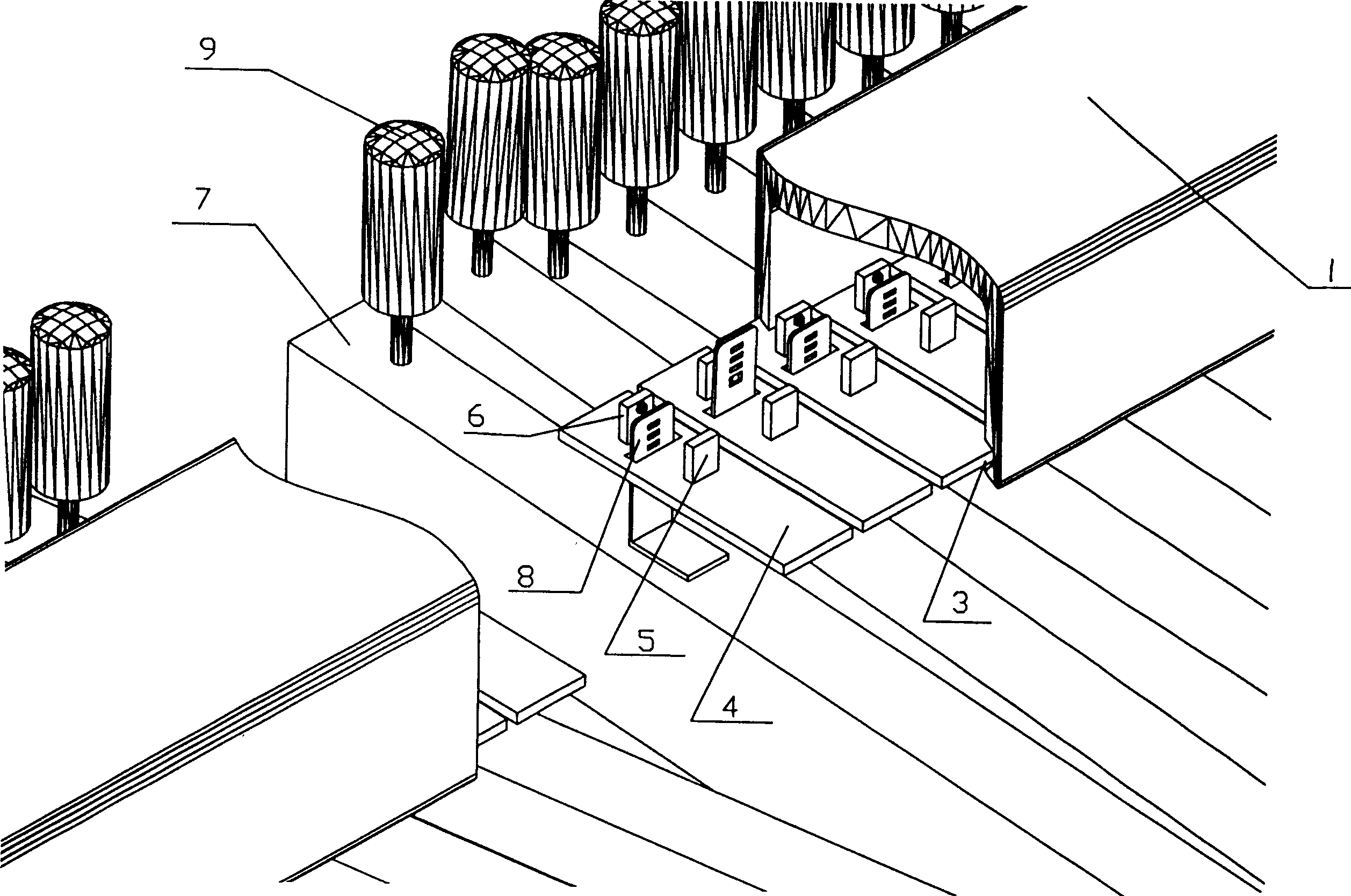
[0019] The basic structure of the photoelectric digital detection device for the action of the piano keyboard in this embodiment is as follows: figure 1 As shown, the detection rod 1 located between the key holder 10 and the top column 9 is supported on the brackets 2 at both ends, and the brackets 2 are fixed on the piano frame. The specific installation conditions in the detection device are as follows: figure 2 As shown, a slip groove 3 is formed in the detection rod 1, and unit detection parts 4 opposite to each key 7 are housed in the groove, and each unit detection part 4 is connected with a relative infrared light emitting device 5 and an infrared light receiving device. device6. In this way, the installation positions of the infrared light emitting device 5 and the infrared light receiving device 6 can be adjusted conveniently according to the grouping of the keys and the change of the key width, so as to adapt to pianos of various models and specifications. The gra...

Embodiment 2

[0025] The basic situation of this embodiment is basically the same as that of Embodiment 1, the main differences are:

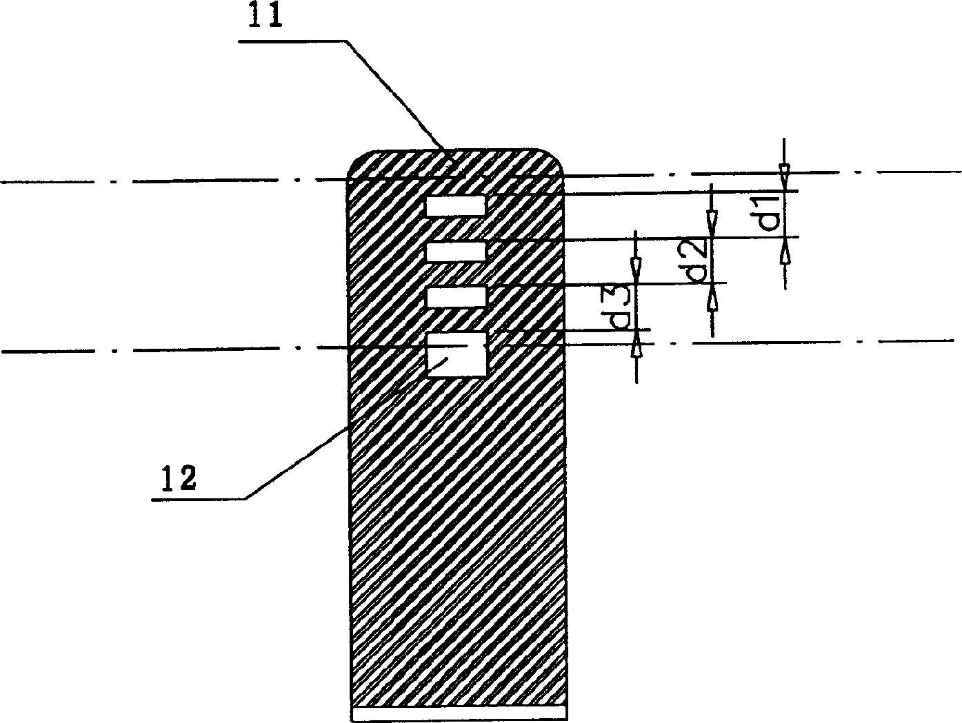
[0026] 1. The upper limit position of the grating 8 corresponds to the light-passing state of the first light hole (or outside the edge of the first light bar of the grating), and the lower limit position corresponds to the last light bar, which is a light-blocking state;

[0027] 2. The detection unit circuit such as Figure 10 As shown, the current input end of the infrared light emitting device 5 is connected to the power supply, and is in a constant light state. The output end of the infrared light receiving device 6 is connected in series with the switching transistor and then connected to the column line of the matrix circuit, and the control pole of the switching transistor is connected to the matrix circuit. The row lines are connected to form Figure 5 The matrix circuit shown, which can make the response speed of the whole detection circuit faster...


PUM


Abstract

The device consists of signal collecting component connecting with piano frame and fingerboard separately. The component comprises components of light-emitting and light-receiving as well as grating which is set in between the two components and can be moved relatively with them. The two components and the grating are moved relatively following the movement of fingerboard moving relatively to the piano frame so the light signal from light-emitting component can be received by light-receiving component through grating which is moved relatively to convert operation parameter to be relevant pulse digital signals of playing strength, up and down direction, state and key playing speed for post processing by computer and circuit in order to output detection result accurately.

Description

technical field [0001] The invention relates to a musical instrument playing detection device, in particular to a detection device for piano keyboard actions. Background technique [0002] The piano playing action detection device can reflect the level of piano playing by monitoring the movement state, direction, and speed of the keys and pedals (that is, the notes played and their strength, duration, and sound stop effect), so as to guide or judge Many occasions such as piano performance, production of electronic piano keyboard or multimedia digital keyboard, and inspection of piano quality provide evidence for people. According to the applicant's understanding, the existing piano keyboard action detection devices mainly include electromagnetic induction type and reed type. The former converts the action of the keyboard into electrical signals during the playing process through the electromagnetic induction elements that are relatively fixed to the piano frame and the keys...

Claims


Application Information

Patent Timeline
Patent Type & Authority Applications(China)
IPC IPC(8): G10C3/00
Inventor 孙玮
Owner 孙玮
Why Eureka
Try Eureka