Method for determining moving distance and direction for optical director

A technology of optical pointing and moving distance, applied in the input/output of user/computer interaction, the input/output process of data processing, instruments, etc., which can solve problems such as production cost burden

Inactive Publication Date: 2003-11-26
ELAN MICROELECTRONICS CORPORATION
View PDF0 Cites 1 Cited by
  • Summary
  • Abstract
  • Description
  • Claims
  • Application Information

AI Technical Summary

Problems solved by technology

[0002] As we all know, the popular ball-less optical mouse (Ball-less optical mouse) is mainly used to compare the difference between two images. Thousands of images, and then compare the differences between the images. This conventional optical mouse design must have hardw

Method used


Image

  • Method for determining moving distance and direction for optical director
  • Method for determining moving distance and direction for optical director
  • Method for determining moving distance and direction for optical director

Examples


Embodiment Construction

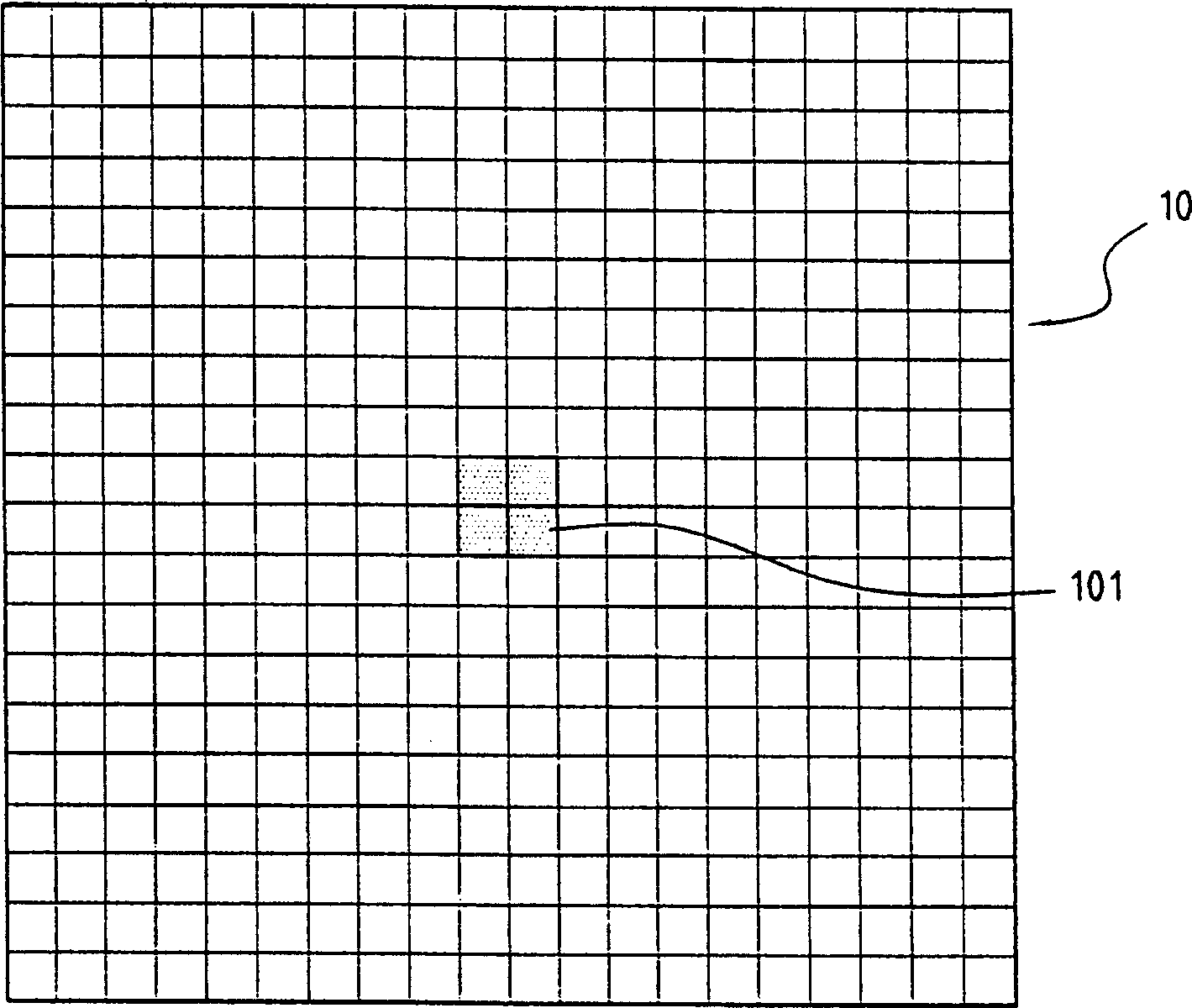
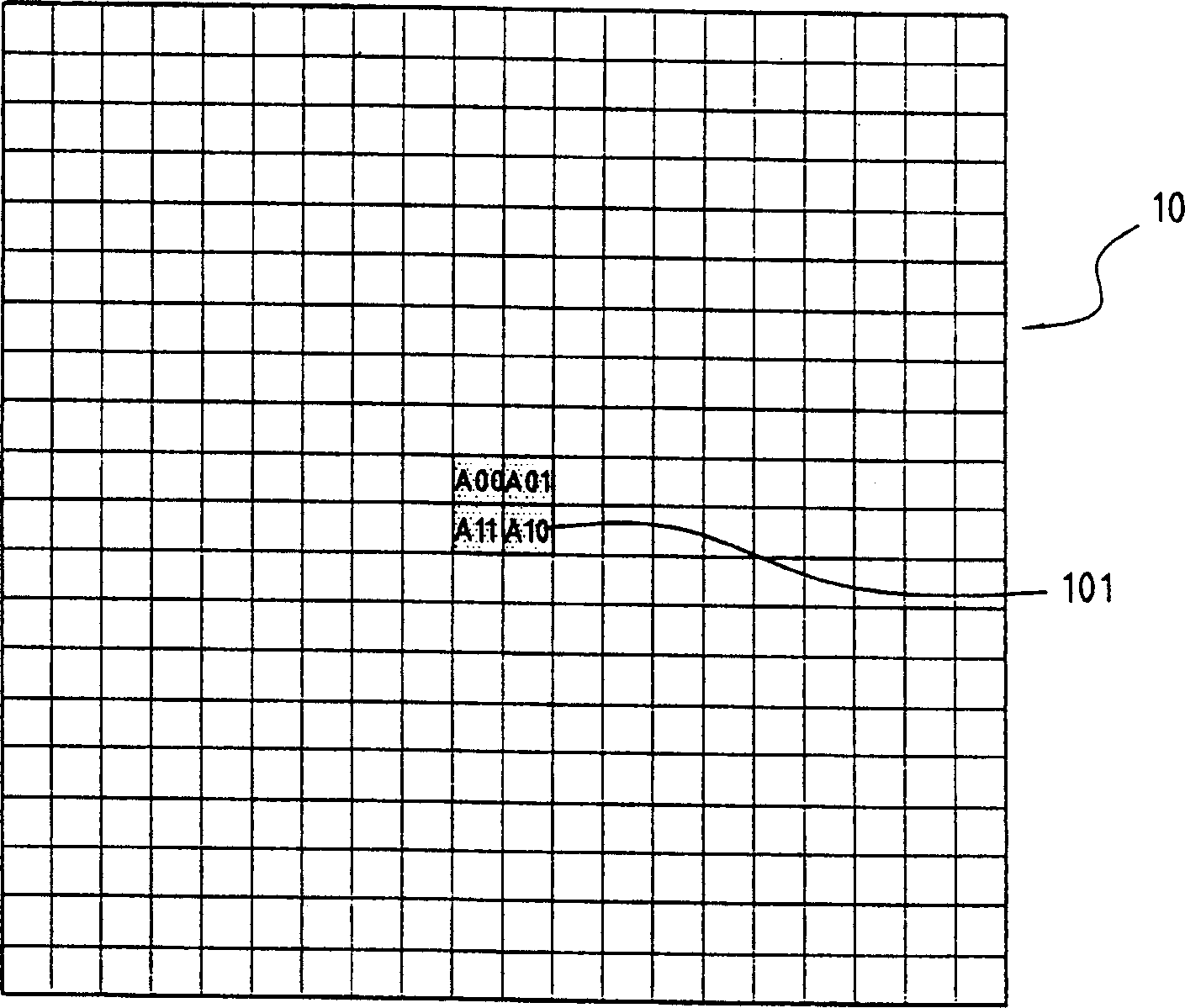
[0019] The present invention is based on considerations of memory requirements and calculation speed. In terms of memory requirements, without affecting the results, the present invention minimizes the memory usage requirements. Through a specific pixel sampling method, the memory usage requirements can be saved. The chip implemented according to the present invention can achieve the purpose of saving the area of ​​the chip and further saving the cost of the chip. In terms of calculation speed, although the present invention inevitably needs to process thousands of images per second, the bottleneck of the method proposed by the present invention is not in the processing of the entire image comparison, but in the optical photosensitive element itself. According to the method proposed in the present invention, the optical photosensitive element is preferably a CMOS image sensor, but when implementing the method of the present invention, the CMOS image sensor is one of the embodim...


PUM


Abstract

The present invention relates to one image comparing method for optical director, and several pixels in the center of the image are used as comparison target so that the optical indicator may be manufactured in lower cost while considering memory requirement and calculation speed. The method of the present invention includes the steps of: sampling the several pixels in the center of the image Pn; comparing the sampled pixels with those in the comparison area formed through expanding from the central pixels by M pixels in both horizontal and vertical directions in the image Pn+1; and calculating the moving distance and direction of the optical director between the image Pn and the image Pn+1.

Description

field of invention [0001] The present invention relates to a method for image comparison of an optical pointing device, and in particular to using a plurality of pixels in the center of the image as the object of comparison, so that the optical pointing device implemented according to the present invention can reduce memory requirements and calculations. Under the consideration of speed, it can be realized by saving more production costs. Background of the invention [0002] As we all know, the popular ball-less optical mouse (Ball-less optical mouse) is mainly used to compare the difference between two images. Thousands of images, and then compare the differences between the images. This conventional optical mouse design must have hardware circuits with a large number of numerical calculations and a large amount of memory because it needs to process thousands of images per second. To meet the requirements of the timing specification (Timing Specific...

Claims


Application Information

Patent Timeline
IPC IPC(8): G06F3/03
Inventor 蔡坤隍
Owner ELAN MICROELECTRONICS CORPORATION
Why Eureka
Try Eureka