Sealing in hydraulic turbine unit

A technology for turbines and sealing rings, which is applied to the sealing of engines, mechanical equipment, engine components, etc., and can solve problems such as inability to center

Inactive Publication Date: 2003-11-26
DIPL ING DR TECHN GITTLER PHILIPP
View PDF3 Cites 14 Cited by
  • Summary
  • Abstract
  • Description
  • Claims
  • Application Information

AI Technical Summary

Problems solved by technology

In fact there are other problems, that is, in trying to get a small amount of leakage, almost no peace of mind

Method used


Image

  • Sealing in hydraulic turbine unit
  • Sealing in hydraulic turbine unit
  • Sealing in hydraulic turbine unit

Examples


Embodiment Construction

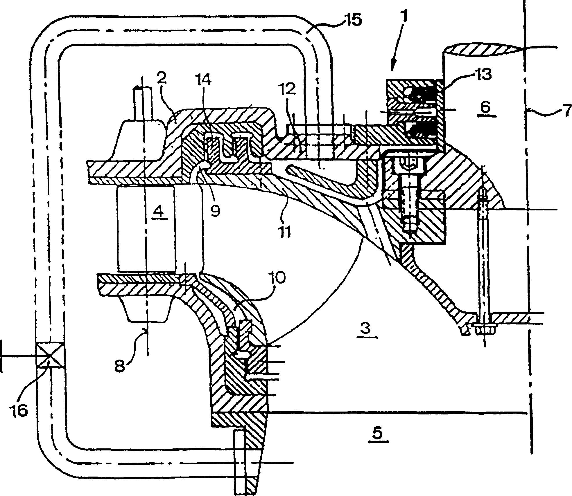
[0028] figure 1 A Francis turbine 1 according to the prior art as known from the book "Rabe, Hydraulische Maschinen und Anlagen" is shown schematically.

[0029] An impeller 3 rotates in a housing 2 through which water flows in via a guide wheel 4 or its separate blades which are rotatable but mounted in the housing 2 with a fixed shaft 8 . The impeller 3 comprises delivery channels extending in the circumferential direction and running curved relative to the turbine shaft 7 , so that the water leaves the impeller 3 approximately axially downwards into the suction pipe 5 .

[0030] Of course, there is an upper gap or gap 9 and a lower gap or gap 10 between the fixed housing 2 and the impeller 3 . The underseam leads to a loss of interstitial water, which flows into the area of ​​the suction pipe without the energy it contains being able to do work, but other than this loss, there are no other problems.

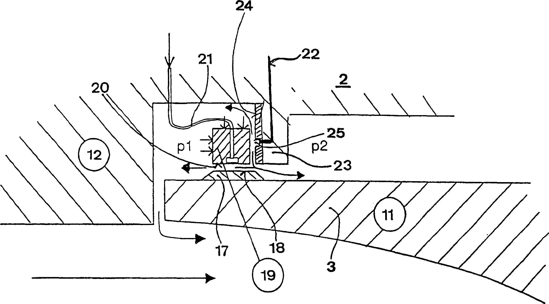
[0031]This is in contrast to water flowing into the upper gap 9 between...


PUM


Abstract

The invention relates to the sealing of the rotor (3) of a hydraulic turbine unit against the turbine housing (2) by means of a seal. The sealing is characterised whereby a floating sealing ring (19) is arranged in the peripheral region of the rotor (3), supported on the rotor (3) and on the turbine housing (2), by means of at least one hydrostatic bearing. In one embodiment the pressurised water for supporting the sealing against the rotor is fed from the bearing for the sealing ring against the turbine housing, by means of the freely rotating sealing ring (19).

Description

technical field [0001] The present invention relates to the sealing of impellers of hydraulic turbines such as turbines, pump turbines, accumulator pumps or other pumps against a turbine housing. Background technique [0002] Kaplan turbines for small drops, Francis turbines for medium drops and Pelton turbines for large drops constitute the current standard index in the field of turbine construction. Here, the Francis turbine basically covers a drop height of 30m-400m. [0003] Furthermore, Francis turbines achieve efficiencies of about 95% in the range of small head heights and higher than 92% in the range of head heights. Especially in the range of large drops, the hitherto unresolved reduction in efficiency is caused by gap losses and disc friction. To illustrate these two phenomena, the construction and operation of the Francis turbine are briefly discussed below. [0004] In a Francis turbine, the water that drives the turbine flows out of a horizontal spiral throug...

Claims


Application Information

Patent Timeline
Patent Type & Authority Applications(China)
IPC IPC(8): F03BF03B11/00F03B11/06F16J15/34F16J15/44
CPCY02E10/226F16J15/342F05B2240/53F03B11/006F16C32/06F16J15/441Y02E10/20F03B11/00F16J15/34F16J15/44
Inventor 菲利普·吉特勒
Owner DIPL ING DR TECHN GITTLER PHILIPP
Why Eureka
Try Eureka