Rocket power assisted launcher and its method

A launcher and booster technology, which is applied in the field of rocket-assisted launchers, can solve the problems of high cost and low rocket carrying capacity, and achieve the effects of reducing launch costs, saving fuel consumption, and avoiding losses

Inactive Publication Date: 2003-12-03
孙学年
View PDF0 Cites 22 Cited by
  • Summary
  • Abstract
  • Description
  • Claims
  • Application Information

AI Technical Summary

Problems solved by technology

Generally, the launch vehicle is 30-100 meters high, 3-4 meters in diameter, and weighs hundreds of tons to thousands of tons. Except for the rocket body and engine, more than 80% of the weight of su

Method used


Image

  • Rocket power assisted launcher and its method
  • Rocket power assisted launcher and its method
  • Rocket power assisted launcher and its method

Examples


Embodiment Construction

[0025] The following is a further explanation in conjunction with the drawings:

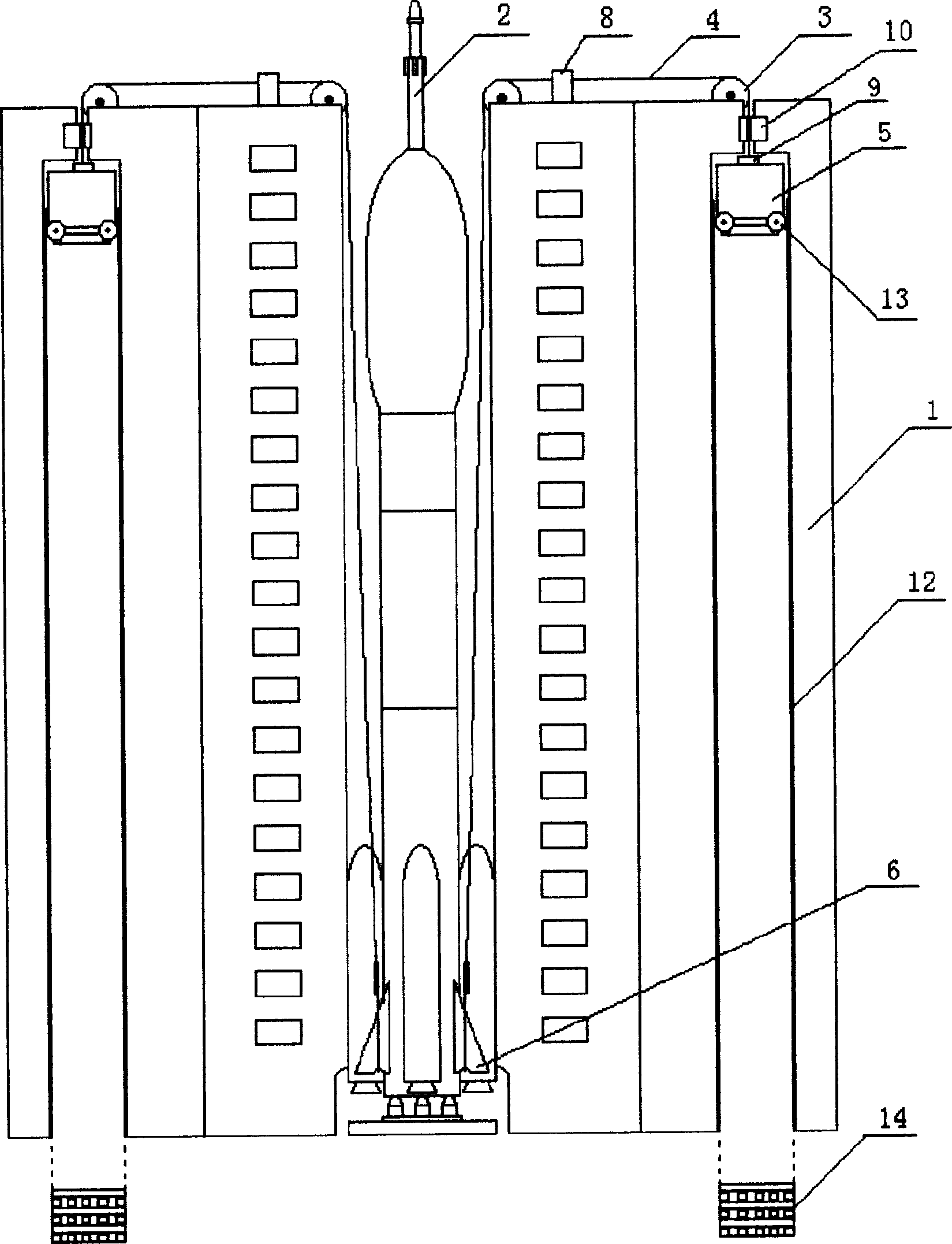
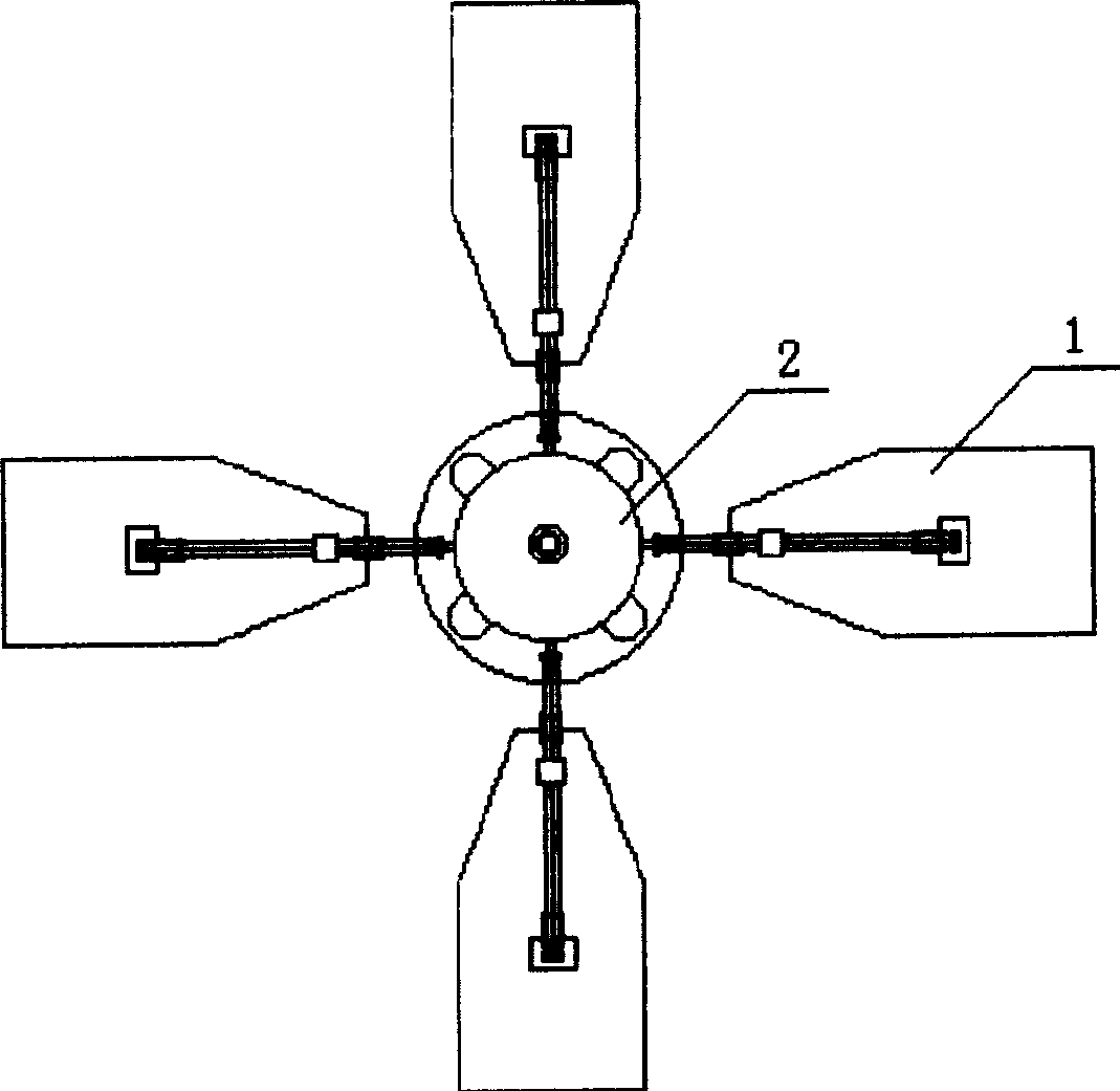
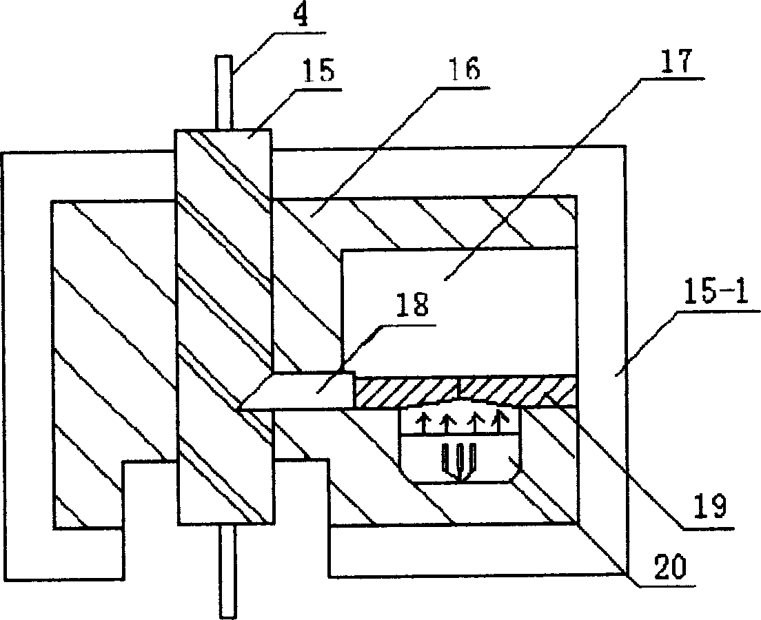
[0026] The first embodiment. The rocket booster launching device of the present invention includes a launching stand 1 and a rocket 2 located inside the launching stand 1, which is also equipped with a boosting device. The boosting device is a wire rope that is equipped with two fixed pulleys 3 on the top of the launching stand 1 and bypasses the fixed pulleys 3. One end of 4 is connected to a weight body 5 that can fall along the vertical track 12, and the weight body 5 is equipped with a guide wheel 13 that matches the vertical track 12. The other end of the wire rope 4 is connected to the rocket body in a detachable manner. The rocket 2 wire rope 4 After the weight body 5 is connected, the weight body 5 is located at the top dead center of the upper part of the launch frame 1. There are three wire ropes 4 in parallel, and the launching frame 1 is all located on the ground. The connection between t...


PUM


Abstract

A boosting launcher of rocket for increasing the effective load of rocket is composed of launching frame and rocket. Its booster consists of the fixed pulley on the top of launching frame, steel cables and counterweights which can vertically drop downwards or slide downwards along a slope. Said steel cable is connected with the counter weight at its one end and with the top of rocket in detachable mode by its other end. Its advantages are simple structure and high boosting effect.

Description

Technical field [0001] The invention relates to the launching technology of rockets, missiles with rocket engines, space shuttles, spacecrafts or other spacecrafts, in particular to a rocket assisted launching device and its method, which can significantly increase the payload of the rocket. Background technique [0002] The prior art closest to the technical solution of the present invention is could launching. The so-called cold launch is the launching method in which the missile is ejected from the launch tube with the aid of auxiliary power, and the main engine is ignited when the missile reaches a certain height. The missile and its launching equipment are not affected by the high temperature generated by the main engine of the missile, so it is called cold launch. The ejection technology of cold launch was first used for torpedo launching. The auxiliary power device installed on the launching equipment is called the external power ejection, and the auxiliary power device is...

Claims


Application Information

Patent Timeline
IPC IPC(8): F41F5/00
Inventor 孙学年
Owner 孙学年
Why Eureka
Try Eureka