Rotary working table of rotary reflector type distribution photometer

A technology of goniophotometer and rotary table, which is applied in the direction of photometry, optical radiation measurement, measuring device, etc., can solve the problems affecting the measurement accuracy, and achieve the effect of high measurement accuracy and convenient use

Inactive Publication Date: 2003-12-10
ZHEJIANG UNIV
View PDF0 Cites 16 Cited by
  • Summary
  • Abstract
  • Description
  • Claims
  • Application Information

AI Technical Summary

Problems solved by technology

In the existing GMS-1800 horizontal goniophotometer, the lamp must be flipped and moved during the measurement process, while the R100 moving reflector type goniophotometer has a fixed measure

Method used


Image

  • Rotary working table of rotary reflector type distribution photometer
  • Rotary working table of rotary reflector type distribution photometer

Examples


Embodiment Construction

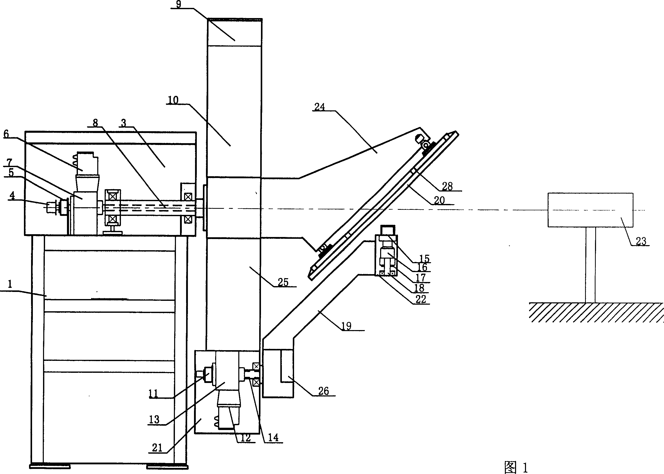
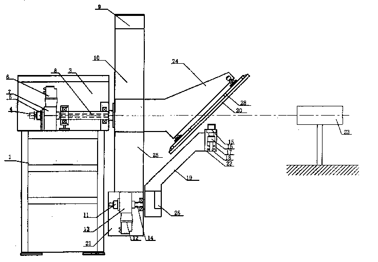
[0011] With reference to Fig. 1, the rotary table of the rotating mirror type goniophotometer of the present invention comprises base 1, is fixed on the main shaft drive box 3 on the base 1, utilizes bearing support to be installed with horizontal main shaft 8 in the main shaft drive box 3, here For example, the main shaft 8 adopts a hollow shaft, and a conductive slip ring 5 and a goniometer 4 for detecting the rotation angle are installed on the hollow shaft. The main shaft 8 is driven to rotate by a motor 6 with a reducer 7 placed in the box. Go out on the flange of the main shaft 8 end faces of driving box 3 and be fastened with boom 25 and cantilever 24, boom 25 is perpendicular to main shaft 8, and the centerline of cantilever 24 coincides with the axis of main shaft 8. The other end of the cantilever 24 is fixed with a reflector frame 28, and the mirror surface of the reflector 20 installed on the reflector frame forms an angle of 45 degrees with the axis of the main sha...


PUM


Abstract

The rotary working table of the distribution photometer includes base seat and horizontal rotary main shaft fixed on the base seat, one end of the main shaft is fastened with large arm and one end of cantilever, the large arm is perpendicular to main shaft, the center line of the cantilever is coincided with axis of main shaft, another end of the cantilever is equipped with a reflector, and another end of the large arm is equipped with a synchronous rotating shaft, one end of the synchronous ratating shaft is fixed with one end of lamp arm, and another end of the lamp arm is equipped with a vertical rotating shaft for connecting lamp.

Description

technical field [0001] The invention relates to a rotating mirror table for photometric measurement. Background technique [0002] The distribution of light in all directions in space is an important parameter for light sources and luminaires. There are usually two ways to measure the light distribution of light sources and lamps. One is to fix the lamp, and the detector moves around the lamp in all directions in space to measure the light signals in all directions. The other is that the detector is fixed, the lamp rotates around the horizontal axis or the vertical axis, and the light signals of the lamp in all directions are projected onto the detector, so as to measure the light distribution in all directions in space. However, in the measurement of spatial light distribution of lamps, there are special restrictions for different lamps. For example, for many high-intensity discharge lamps, the lamps are not allowed to turn over and move during th...

Claims


Application Information

Patent Timeline
IPC IPC(8): G01J1/02
Inventor 牟同升
Owner ZHEJIANG UNIV
Why Eureka
Try Eureka