Supercharge Your Innovation With Domain-Expert AI Agents!

High frequency heater

A high-frequency heating device and heating chamber technology, which is applied to electric heating devices, microwave heating, and electric heating of fuel, etc., can solve the problems of high material cost, poor cooling efficiency of high-voltage capacitors 2, and reduced assembly efficiency.

Inactive Publication Date: 2003-12-24
PANASONIC CORP
View PDF1 Cites 1 Cited by
  • Summary
  • Abstract
  • Description
  • Claims
  • Application Information

AI Technical Summary

Problems solved by technology

The cooling air flow turned back from the high-voltage transformer 6 becomes a high-temperature air flow due to absorbing the heat on the high-voltage transformer 6, thus causing the problem that the cooling efficiency of the high-voltage capacitor 2 is very poor
[0011] In addition, in Figure 9 In the existing structure in which the insulation cover 8 is additionally installed as shown, due to the increase of the insulation cover 8, the number of components increases, and the assembly efficiency will also decrease.
In addition, since the rectification function of the cooling air flow is added, the insulating cover plate 8 will become a very large part, and the material cost will also become high like this.

Method used


Image

  • High frequency heater
  • High frequency heater
  • High frequency heater

Examples


Embodiment 1

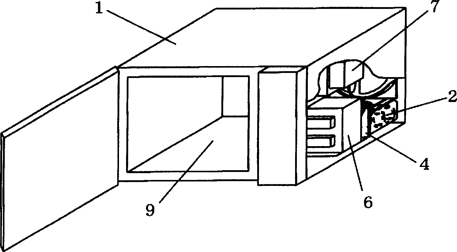
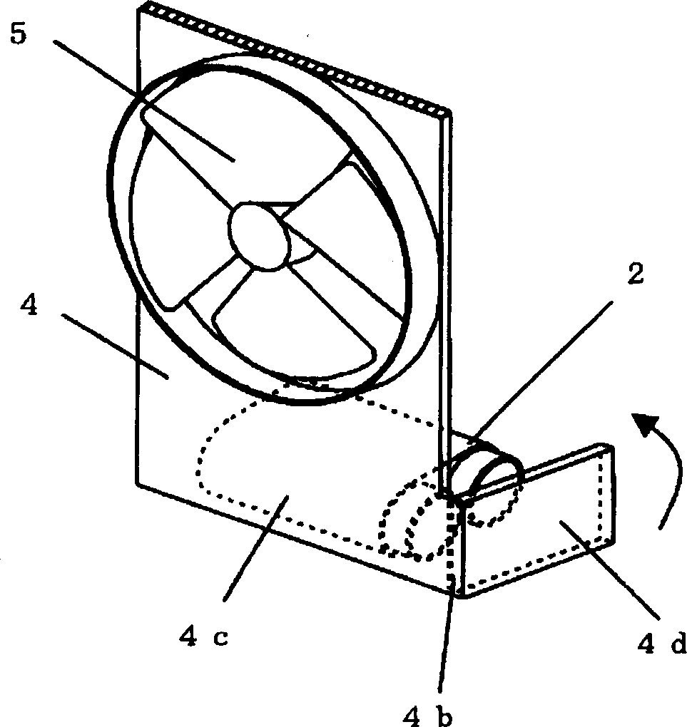
[0036] Figure 1 to Figure 3 shows the high-frequency heating device in the first embodiment of the present invention, figure 1 Its oblique cross-sectional view, figure 2 An enlarged schematic diagram of its main components, image 3 A cross-sectional view of its main components.

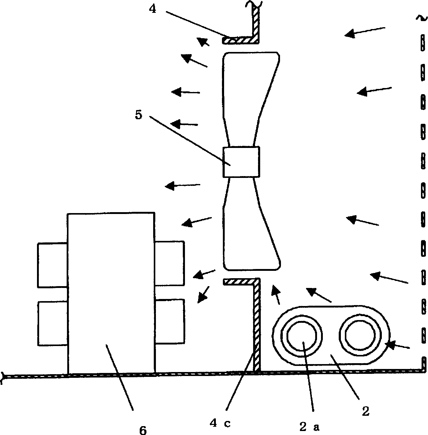
[0037] Figure 1 to Figure 3 Among them, 9 is a heating chamber, and the high-voltage capacitor 2 and the high-voltage transformer 6 supply the boosted power to the magnetron 7, and the food placed in the heating chamber 9 is heated. The air guiding member 4 has a partition wall 4c between the high-voltage transformer 6 and the high-voltage capacitor 2. The partition wall 4c is provided with a resin hinge 4b ​​with a partially thinned thickness. When the resin hinge 4b ​​is bent, its front end portion 4d It will be between the terminal part 2a of the high-voltage capacitor 2 and the housing cover 1 which is a non-charging metal.

[0038] As described above, in this embodiment, the resin hinge...

Embodiment 2

[0041] Figure 4 It is an enlarged schematic view of the main components of the air guide member 4 provided with the resin hinge 4b ​​and the high voltage capacitor 2 in the second embodiment of the present invention. The front end part 4d is on the movement track when the casing cover 1 is installed, and the resin hinge 4b ​​will be bent as the operation of installing the casing cover 1 is carried out. This point is different from Example 1. In addition, the same constituent elements as those in Embodiment 1 are assigned the same symbols, and their descriptions are omitted.

[0042] First, when the housing cover 1 is attached, the housing cover 1 contacts the front end portion 4d of the air guide member 4 on its mounting track, bending the resin hinge 4b. As a result, the front end portion 4d bent at the resin hinge 4b ​​will protrude between the terminal portion 2a of the high voltage capacitor 2 and the case cover 1 which is a non-charging metal. The electrical insulatio...


PUM


Abstract

To provide a high-frequency heating device capable of stably securing electric insulation, improving cooling efficiency of a high voltage capacitor, and realizing the reduction of work man-hours in manufacturing processes and waste. This high-frequency heating device is provided with an enclosure cover 1, a high voltage generating means such as the high voltage capacitor 2, and an air guide 4. On the air guide 4, a resin hinge 4b that is locally thin is formed. By folding the resin hinge 4b, a tip part 4d of the air guide 4 can be positioned between a terminal part 2a and the enclosure cover 1 of non-charging metal. Electric insulation can thus be easily secured between the terminal part 2a and the enclosure cover 1 regardless of irregularity of work n the manufacturing processes. Since the resin hinge 4b need be folded only, the manufacturing processes can be reduced, and the waste can be reduced.

Description

technical field [0001] The present invention relates to a high-frequency heating device in which resin hinges are bent or a casing cover is mounted after wiring is completed to terminals with high voltage, such as terminals of high-voltage transformers and high-voltage capacitors. The resin hinge can be automatically bent during boarding, so that the housing cover can be made Electrical insulation is easily and reliably achieved between the non-chargeable metal that can be touched by the user and the terminal portion with high voltage. Background technique [0002] In the existing high-frequency heating device, in order to ensure electrical insulation, the non-charged metal part (referring to the metal part that is not charged when the device is working) and the high-voltage capacitor terminal that the user can touch, such as the shell cover plate, are generally separated. The distance between the parts is enlarged, or if the distance cannot be enlarged, an insulating mater...

Claims


Application Information

Patent Timeline
Patent Type & Authority Applications(China)
IPC IPC(8): H05B6/66F24C7/02H05B6/64H05B6/80
CPCH05B6/642
Inventor 山口崇任
Owner PANASONIC CORP
Features
  • R&D
  • Intellectual Property
  • Life Sciences
  • Materials
  • Tech Scout
  • Unparalleled Data Quality
  • Higher Quality Content
  • 60% Fewer Hallucinations
Learn More