Combustor

A technology of burners and gas turbines, which is applied in the direction of burners, combustion chambers, gas fuel burners, etc., and can solve the problems of increasing the number of injection holes, interfering with air flow, and difficulty in supplying air

Inactive Publication Date: 2003-12-31
MITSUBISHI HEAVY IND LTD
View PDF1 Cites 38 Cited by
  • Summary
  • Abstract
  • Description
  • Claims
  • Application Information

AI Technical Summary

Problems solved by technology

[0009] In the above-mentioned burner disclosed in Japanese Unexamined Patent Publication (Kokai) No. 6-2848, since the diameter of the injection orifice of the hollow column is determined according to the machining accuracy or the hole clogging problem, the injection The increase in the number of orifices is limited
Second, when the number of hollow columns increases, it becomes difficult to supply air to the mixing chamber because each hollow column 250 interferes with the airflow

Method used


Image

  • Combustor
  • Combustor
  • Combustor

Examples


Embodiment Construction

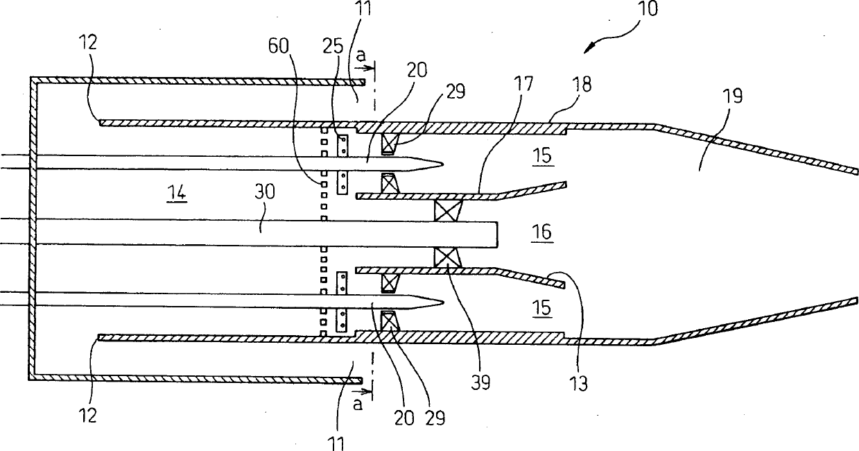
[0027] Some embodiments of the present invention will be described below with reference to the accompanying drawings. In each figure, the same components are denoted by the same reference numerals. The scale of these figures has been changed for ease of understanding.

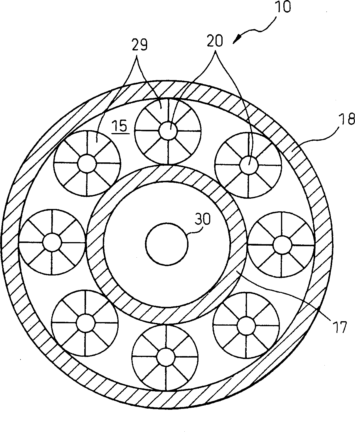
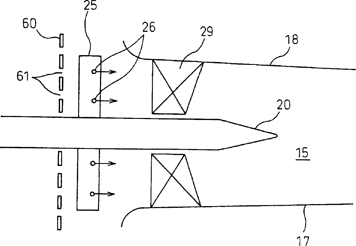
[0028] Fig. 1 shows a partial longitudinal sectional view of a burner according to a first embodiment of the present invention. Fig. 2 is a sectional view taken along the line a-a in Fig. 1 . Similar to the above-described embodiments, a pilot nozzle 30 is disposed on the central axis of the inner tube 18 of a combustor 10 . As can be seen from FIG. 2 , a number of fuel nozzles are spaced equidistantly in the circumferential direction around the priming nozzle 30 . A swirl vane or a swirler 29 is arranged around the rod-shaped body of the fuel nozzle 20 . A plurality of hollow cylinders 25 are provided on the fuel nozzle 20 . The hollow cylinder 25 extends radially outward from the sidewall of the fuel noz...


PUM


Abstract

The invention relates to a combustor comprising an air flow channel for feeding air into the interior, and a fuel nozzle disposed in the air flow channel and having a spout port for spouting fuel, wherein a turbulence generating body adjacent the spout port of the fuel nozzle is installed in the air flow channel. It also relates to a combustor comprising an air flow channel for feeding air into the interior, and a fuel nozzle disposed in the air flow channel and having a spout port for spouting fuel, wherein a diffuser section is installed in the air flow channel, the diffuser section causing the cross sectional area of the portion of the air flow channel positioned in the vicinity of the spout port to be smaller than the cross sectional area of the downstream portion of the air flow channel positioned more downstream than the spout port with respect to the flow of air. Thereby, the generation of combustion vibration is suppressed while enhancing the fuel-air mixing action.

Description

technical field [0001] The present invention relates to a combustor, and more particularly, to a gas turbine combustor for a gas turbine. Background technique [0002] Fig. 11 shows a longitudinal sectional view of a prior art burner incorporating a fuel nozzle disclosed in Japanese Unexamined Patent Application (Kokai) No. 6-2848. As shown in FIG. 11 , a starting nozzle 300 is disposed on the central axis of the inner tube 180 of a combustor 100 . A plurality of fuel nozzles 200 extending substantially parallel to the priming nozzle 300 are equidistantly spaced in the circumferential direction around the priming nozzle 300 . Fuel is supplied to the starter nozzle 300 and each fuel nozzle 200 . A swirler or a swirler 290 is arranged around the rod-shaped part of the fuel nozzle 200 . A plurality of hollow columns 250 extending radially outward from the sidewall of the fuel nozzle 200 are arranged on the fuel nozzle 200 . Each hollow column 250 is connected to the fuel no...

Claims


Application Information

Patent Timeline
Patent Type & Authority Applications(China)
IPC IPC(8): F23R3/10F23D14/02F23D14/70F23R3/14F23R3/28F23R3/32F23R3/34
CPCF23R3/286F23R3/14F23D14/70F23R2900/00014
Inventor 齐藤圭司郎
Owner MITSUBISHI HEAVY IND LTD
Why Eureka
Try Eureka