Supercharge Your Innovation With Domain-Expert AI Agents!

Kerosene stove

A technology of kerosene and combustion chambers, which is applied to household stoves/stoves, combustion methods, heating fuels, etc., and can solve problems such as blocking flames, incomplete combustion, and danger

Inactive Publication Date: 2004-01-07
TOKKYO KAIHATSU YOGEN KAISHA
View PDF0 Cites 1 Cited by
  • Summary
  • Abstract
  • Description
  • Claims
  • Application Information

AI Technical Summary

Problems solved by technology

[0011] On the other hand, in order to avoid this over-combustion state, the protruding amount of the combustion core body 17 can be reduced, or in order to prevent the flame in the above-mentioned combustion chamber 25 from being deflected, the distance between the inner flame tube 23 and the outer flame tube 24 can be adjusted. The gap is narrowed, but like this, the tar-like substance produced due to the incomplete combustion state will accumulate near the top end of the combustion core 17 located at the lower position of the combustion chamber 25, resulting in a further incomplete combustion state.
Moreover, the wire mesh of the special steel wire will also adhere to the coal produced by incomplete combustion, blocking the flames, which is very dangerous

Method used


Image

  • Kerosene stove
  • Kerosene stove
  • Kerosene stove

Examples


Embodiment Construction

[0024] Embodiments of the present invention use Figure 2 ~ Figure 6 To illustrate.

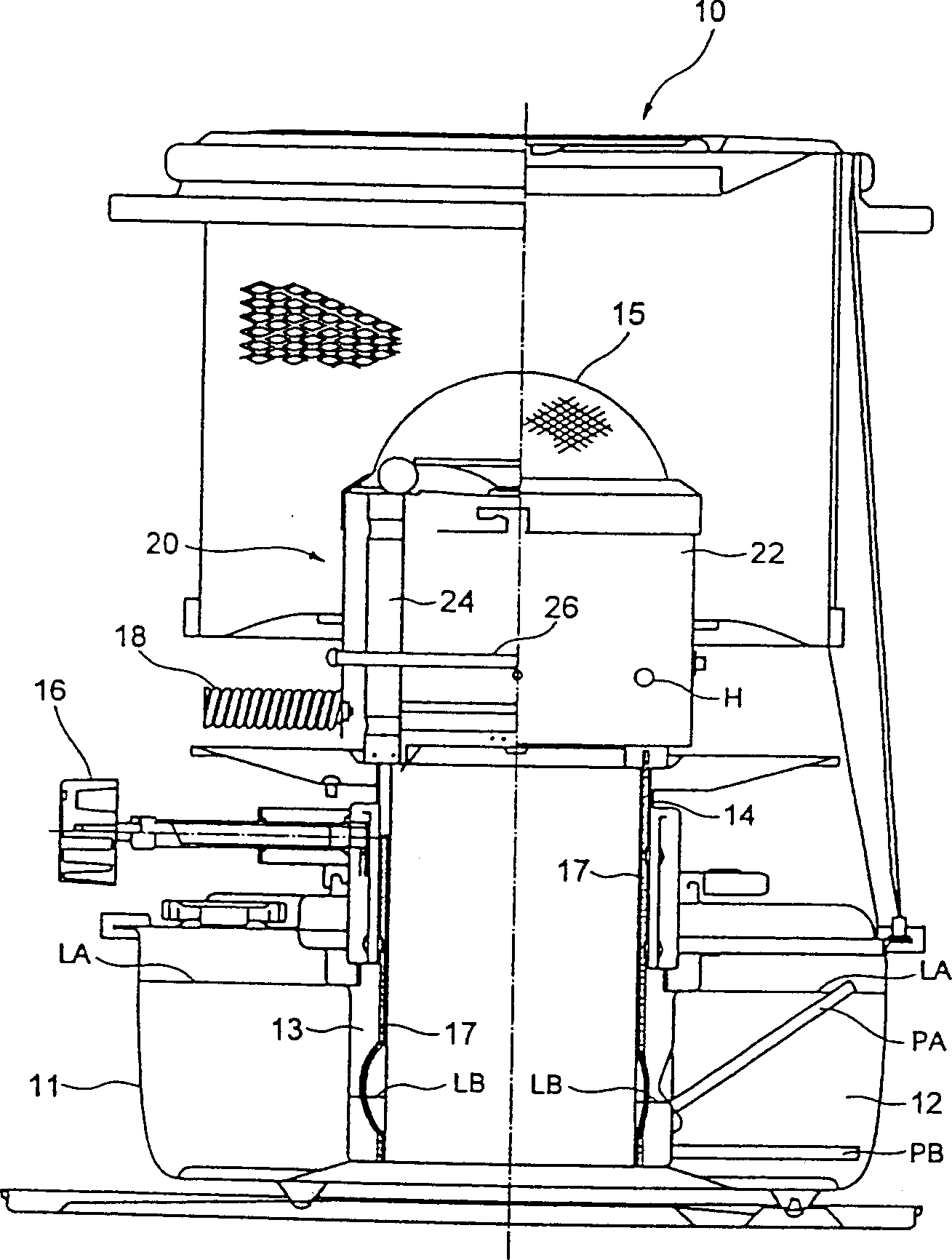
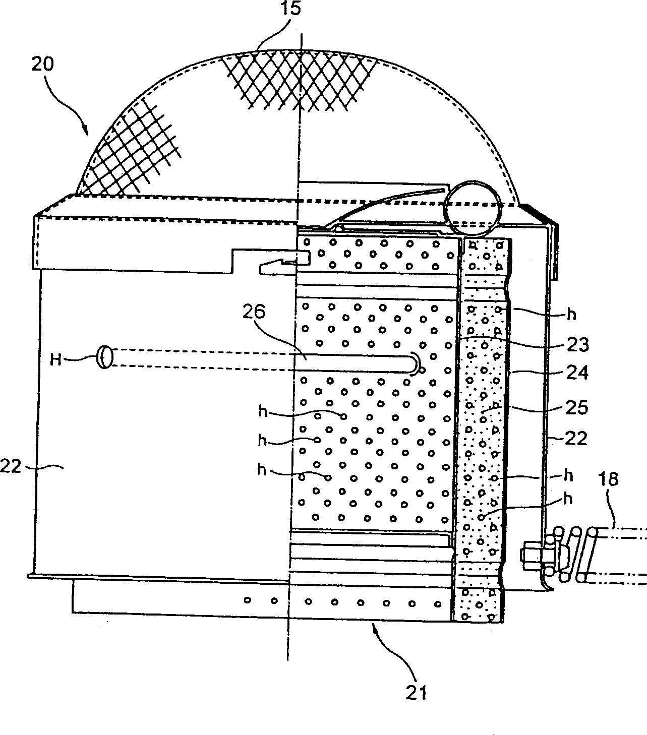
[0025] figure 2 means as mentioned above figure 1 A diagram of the combustion section 20 of the kerosene stove 10 is shown.

[0026] In addition, this combustion unit 20 is equipped with a flame stabilizing wire mesh on the upper part of the outer cylinder 22, and also has a knob 18 for opening and closing the combustion unit. The combustion chamber 25 is a circumferential space formed by the inner flame tube 23 and the outer flame tube 24; at the lower end of the combustion chamber 25, as figure 1 As shown, the top part of the combustion core body 17 is inserted or pulled out by the up and down adjusting knob 16.

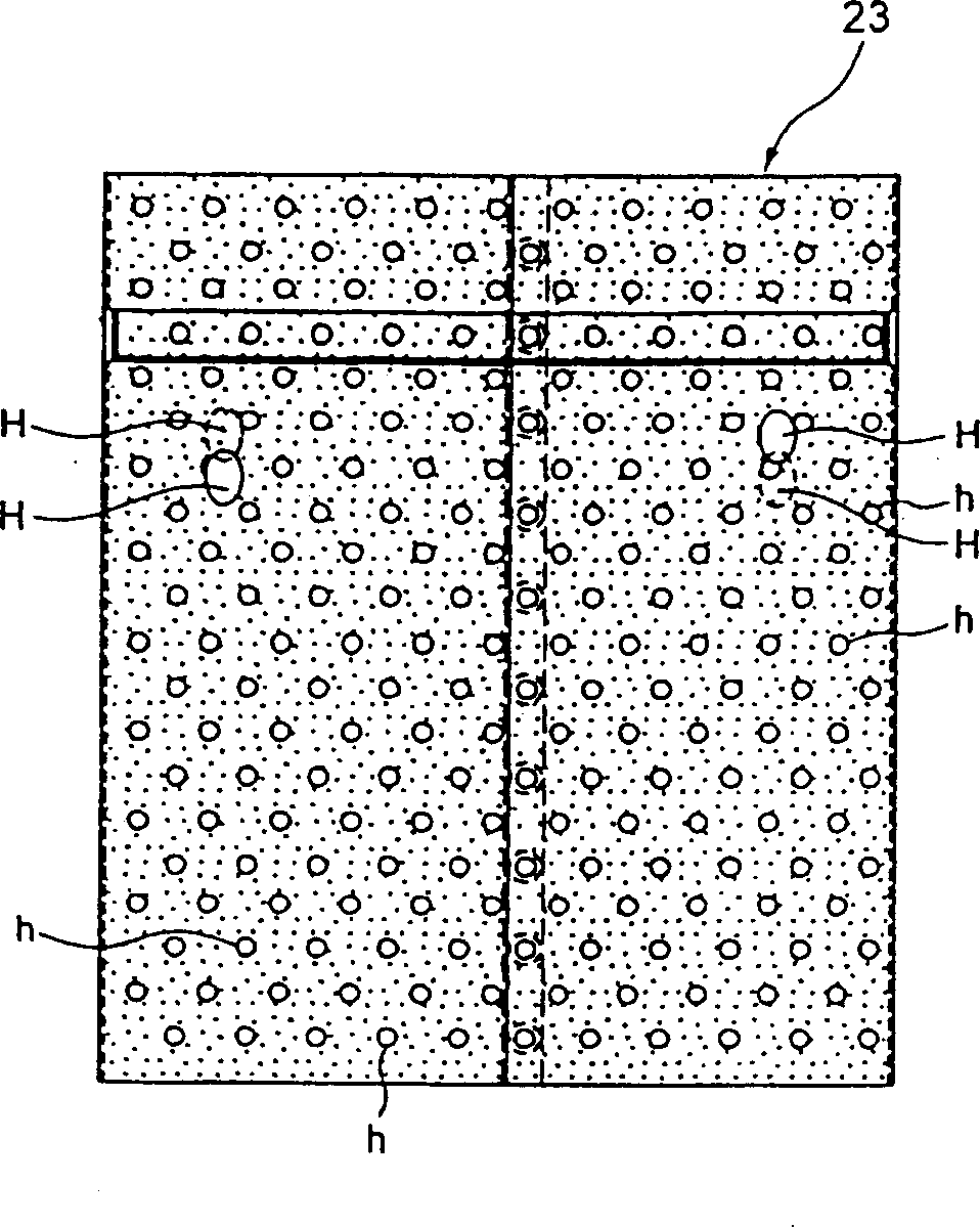
[0027] figure 2 The right half of the above-mentioned combustion part 20 is shown in section. In this figure, the inner flame tube 23 and the outer flame tube 24 each have a plurality of ventilation holes h~h, and air is supplied from the inner and outer sides of the combus...


PUM


Abstract

A kerosene heater is provided with a structure of a combustion chamber capable of continuing combustion in a stabilized flame condition and prevents a state of an incomplete combustion condition perfectly. The kerosene heater of the invention is a type wherein kerosene supplied from a kerosene supply chamber is combusted in a combustion chamber between an inner flame cylinder and an outer flame cylinder positioned in an outer cylinder, respectively, and the kerosene supply chamber and a kerosene storage chamber provided at the outer periphery of the kerosene supply chamber are connected to each other by two communication pipes, wherein blast processing is applied to the inner flame cylinder and the outer flame cylinder at least at the combustion chamber side, which has a rough surface.

Description

technical field [0001] The invention relates to a combustion chamber structure of a kerosene stove, in particular to a combustion chamber surface structure capable of stable and complete combustion and completely preventing flames from burning up. Background technique [0002] figure 1 For example, it is a figure of the whole structure of the same stove as the kerosene stove proposed previously by the inventor of this invention, and shows the outline|summary of the kerosene stove 10. [0003] The fuel tank 11 of the kerosene stove 10 has a kerosene storage chamber 12 and a kerosene supply chamber 13 for supplying kerosene to the wick. The opening 14 of the supply chamber is provided with a kerosene burning core 17, and the lower end of the core is placed on the kerosene supplying chamber. The liquid in the chamber 13 is below the surface, while its upper end faces the combustion chamber 24 of the combustion unit 20 . [0004] In addition, the two communication pipes PA and...

Claims


Application Information

Patent Timeline
Patent Type & Authority Applications(China)
IPC IPC(8): F23D3/10F23D3/02F23D3/20F23D3/22F24C5/00F24C5/06
CPCF23D2213/00F23D3/20F23D3/22F23D3/02F24C5/06
Inventor 大野日佐太
Owner TOKKYO KAIHATSU YOGEN KAISHA
Features
  • R&D
  • Intellectual Property
  • Life Sciences
  • Materials
  • Tech Scout
  • Unparalleled Data Quality
  • Higher Quality Content
  • 60% Fewer Hallucinations
Learn More