Deflection device

A deflection device and vertical deflection technology, applied in the direction of electrode devices and related components, discharge tubes, cathode ray tubes/electron beam tubes, etc., can solve the problems of insignificant differences, increased production costs of deflection devices 1, and increased number of components

Inactive Publication Date: 2004-01-07
SAMSUNG ELECTRO MECHANICS CO LTD
View PDF1 Cites 4 Cited by
  • Summary
  • Abstract
  • Description
  • Claims
  • Application Information

AI Technical Summary

Problems solved by technology

However, since the difference between the central area and the lateral areas (upper and lower corner areas) of the horizontal deflection magnetic field HB is not significant, the electron beams cannot be deflected toward the leftmost or rightmost part of the screen, thereby producing a Pincushion
[0056] One of the above-mentioned problems can be solved by adjusting the winding number of the fourth deflection coil 35d in the vertical deflection coil 30, but it is difficult to form the winding number of the fourth deflection coil 35d according to the number of windings.
[0057] In addition, if permanent magnets or magnetic materials are used to correct the pincushion distortion, the number of parts increases, the production process becomes complicated, and the production cost of the deflection yoke 1 is increased.
[0058] Furthermore, if the cathode ray tube using the deflection device 1 has a flat panel, misconvergence occurs due to the extension of the path for the electron beams to reach the panel 2a

Method used


Image

  • Deflection device
  • Deflection device
  • Deflection device

Examples


Embodiment Construction

[0093] Embodiments of the present invention will now be described in detail with reference to the drawings, wherein like reference numerals are used for like parts throughout the drawings. In order to illustrate the present invention, the embodiments are described below in conjunction with the accompanying drawings.

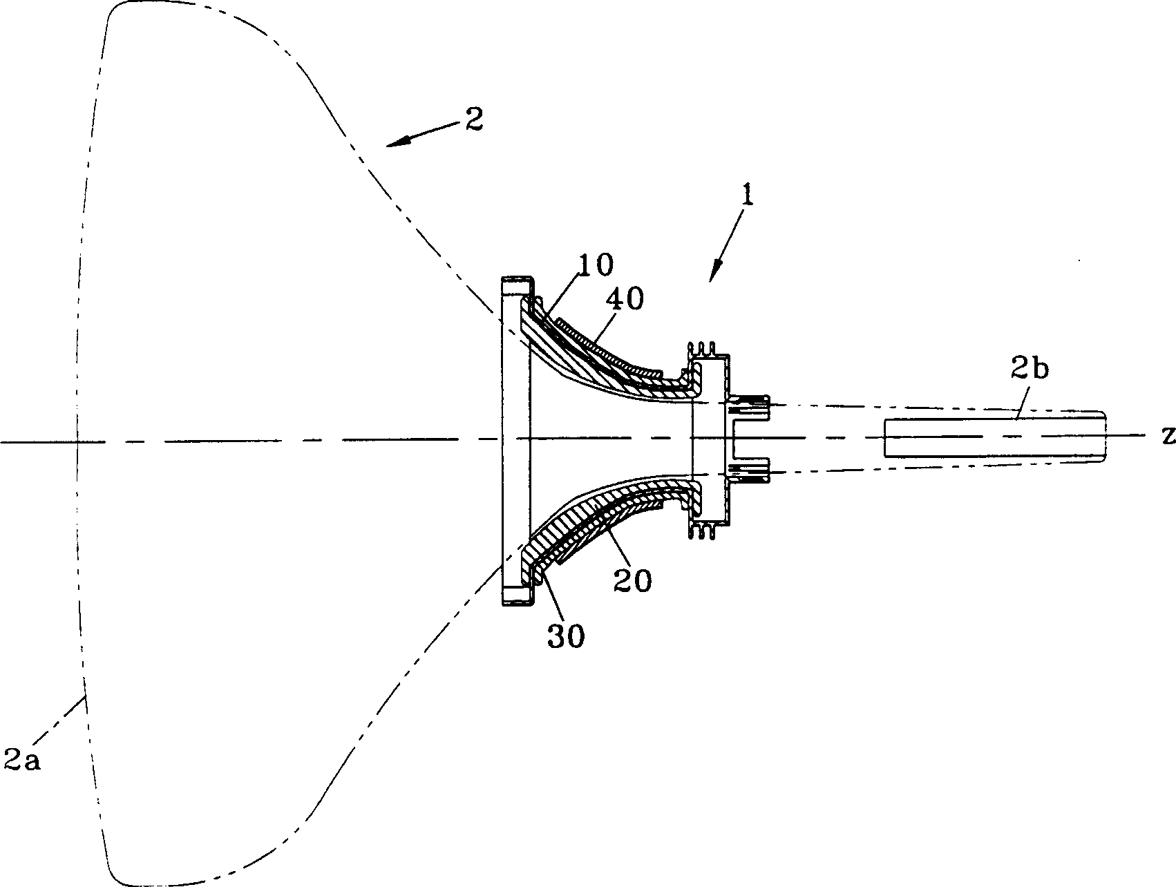
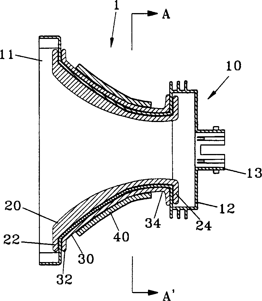
[0094] Figure 11 shows a partial sectional view of a deflection device 100 in a cathode ray tube 2 according to a preferred embodiment of the present invention, while Figure 12 show Figure 11 A cross-sectional view of the deflection device 100 is shown.

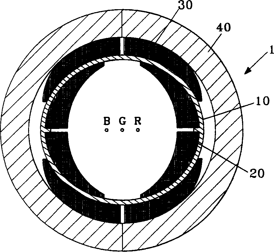
[0095] Such as Figure 11 and 12 As shown, the deflection device 100 comprises a symmetrically placed coil isolator 10 and has a pair of half portions formed as a whole.

[0096] The coil isolator 10 includes a screen portion 11 having a screen plate 2a of the CRT 2, and a neck portion extending from a central portion of the rear cover 12 to be coupled with an electron gun of the CRT 2.

[0097] Inside and...


PUM


Abstract

A deflection yoke attached to a cathode ray tube to deflect an electron beam generated from an electron gun includes a coil separator having a horn shape and electrically insulating deflection coils, a horizontal deflection coil having a pair of upper and lower coils disposed on an inside of the coil separator to generate a horizontal deflection magnetic field to deflect the electron beam in a horizontal direction, a vertical deflection coil having a pair of right and left coils disposed on an outside of the coil separator to generate a vertical deflection magnetic field, having a deflection coil portion and a bent coil portion extended from the deflection coil portion to generate a magnetic field, which is in an opposite direction to another magnetic field generated from a portion of the deflection coil portion disposed adjacent to the bent coil portion and weakens another magnetic field generated from the deflection coil portion, and having a vertical radius and a horizontal radius, which is different from the vertical radius, and a ferrite core having a cylindrical shape covering a portion of the deflection coil portion of the vertical deflection coil to strengthen the vertical deflection magnetic field and the horizontal deflection magnetic field. A magnetic field generated from a corner portion of the vertical deflection coil is weakened to correct the pincushion distortion of the screen as well as the misconvergence.

Description

[0001] Cross References to Related Applications [0002] This application claims the benefit of Korean Patent Application No. 2002-36554 filed with the Korean Intellectual Property Office on June 28, 2002, the disclosure of which is hereby cross-referenced. technical field [0003] The present application relates to a deflection device, in particular to a deflection device for screen distortion compensation. Background technique [0004] In general, the deflection yoke has various types such as saddle toroidal saddle and saddle, etc., according to deflection yokes used in a cathode ray tube (CRT) of a monitor or television. [0005] For example, a winding coil formed in a certain shape is called a saddle or a saddle (winding frame type) deflection coil, and a winding coil formed on a cylindrical ferrite core of magnetic material is called a saddle ring A deflection device, and a winding coil formed on a cylindrical bobbin is called a bobbin deflection device. [0006] Fig....

Claims


Application Information

Patent Timeline
Patent Type & Authority Applications(China)
IPC IPC(8): H01J29/76H01J29/70
CPCH01J29/762H01J2229/7032
Inventor 黄硕焕曹点洙郑喆昊赵英勋河德浩金在丁
Owner SAMSUNG ELECTRO MECHANICS CO LTD
Why Eureka
Try Eureka