Radio frequency bias circuit packaging structure

A technology of radio frequency bias and circuit packaging, which is applied in the direction of radio frequency amplifiers, electrical components, amplifiers with semiconductor devices/discharge tubes, etc. Problems such as large area of ​​circuit board

Pending Publication Date: 2020-10-27
DYNAX SEMICON
View PDF0 Cites 0 Cited by
  • Summary
  • Abstract
  • Description
  • Claims
  • Application Information

AI Technical Summary

Problems solved by technology

[0003] At present, it is difficult to integrate the power amplifier module with other modules. Most of the power amplifier modules are connected to the whole system in the form of a separate module, which makes the power amplifier module occupy a larger size of the wireless communication system, which is not conducive to wireless Miniaturization of the complete communication system
In addition, the traditional power amplifier needs to be equipped with a bias circuit that cooperates with the power amplifier to provide a bias voltage for the power amplifier to perform the amplification function. However, the bias circuit of the power amplifier currently used needs to be introduced on the printed circuit board. Longer bias lines, and longer bias lines occupy a larger area of ​​the printed circuit board, and the integration level of the printed circuit board is low

Method used


Image

  • Radio frequency bias circuit packaging structure
  • Radio frequency bias circuit packaging structure
  • Radio frequency bias circuit packaging structure

Examples


Embodiment Construction

[0023] The present invention will be further described in detail below in conjunction with the accompanying drawings and embodiments. It should be understood that the specific embodiments described here are only used to explain the present invention, but not to limit the present invention. In addition, it should be noted that, for the convenience of description, only some structures related to the present invention are shown in the drawings but not all structures. Throughout this specification, the same or similar reference numerals represent the same or similar structures, elements or processes. It should be noted that, in the case of no conflict, the embodiments in the present application and the features in the embodiments can be combined with each other.

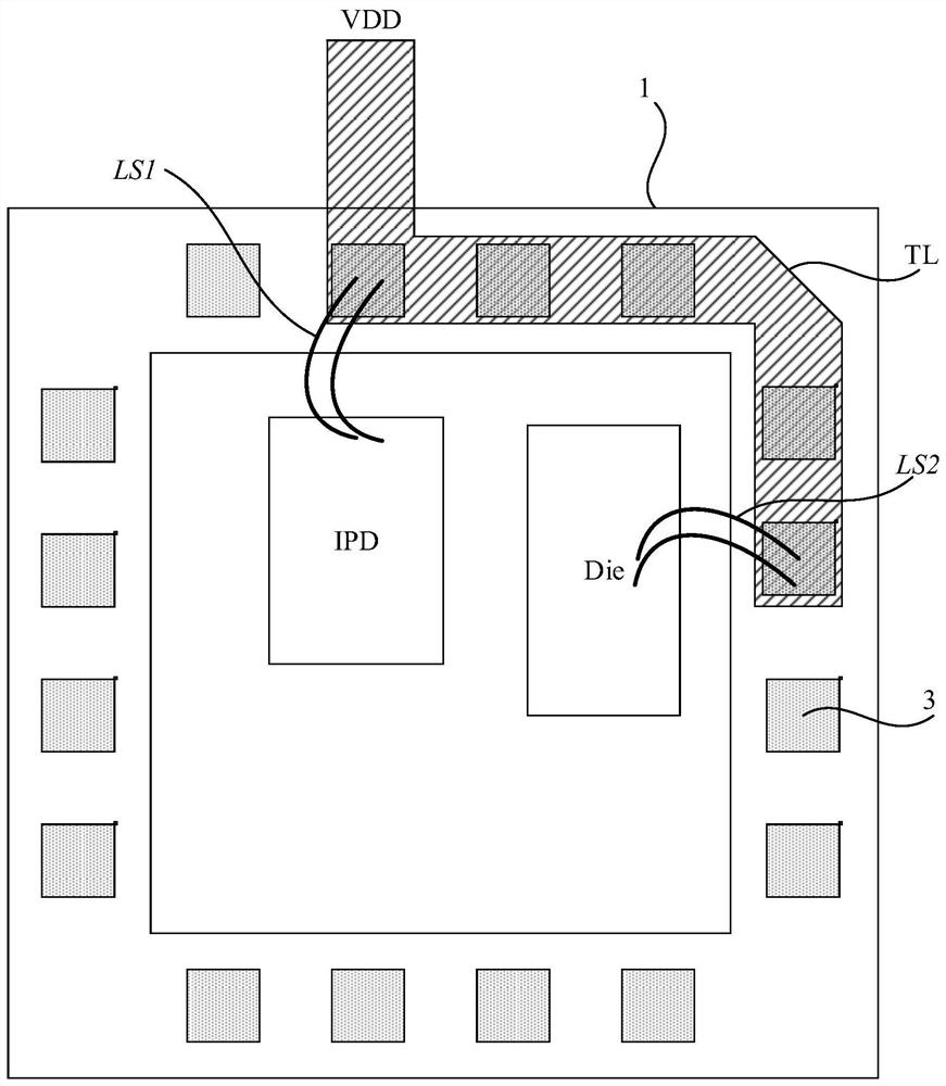
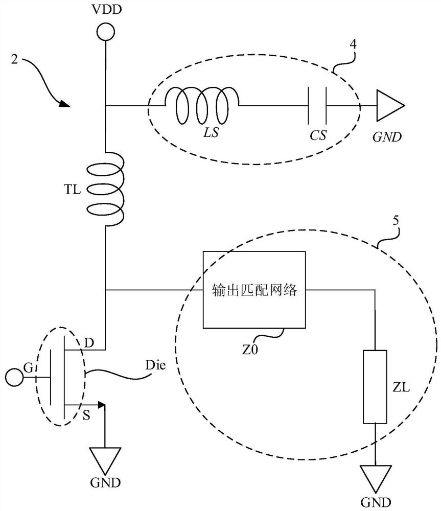
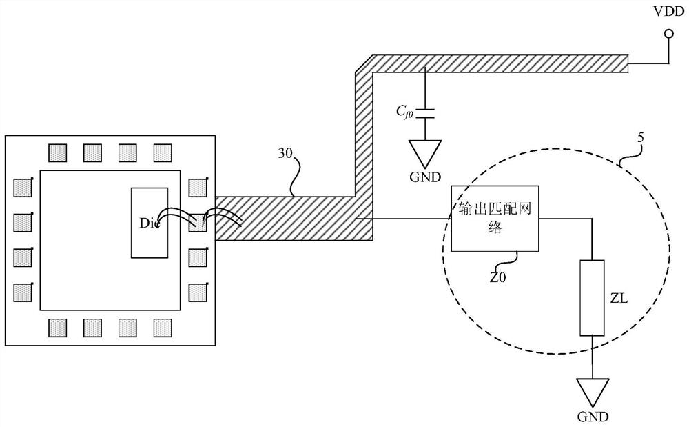
[0024] An embodiment of the present invention provides a radio frequency bias circuit packaging structure, including a packaging component and a radio frequency bias circuit, a power amplifier is packaged in the packagi...


PUM


Abstract

The invention provides a radio frequency bias circuit packaging structure. The radio frequency bias circuit packaging structure comprises a packaging part, and a power amplifier is packaged in the packaging part; the radio frequency bias circuit packaging structure further comprises a radio frequency bias circuit which comprises a radio frequency choke component, and the port, electrically connected with the output load, of the power amplifier is electrically connected with a direct current bias voltage source through the radio frequency choke component; the packaging part covers the radio frequency choke component. According to the technical scheme of the invention, the connection relationship between the radio frequency choke component and the power amplifier is realized; the radio frequency signal is prevented from influencing the characteristics of a direct current bias voltage source, and the problem that the power amplifier module occupies a large area of a printed circuit boarddue to the fact that the radio frequency bias circuit is provided with a long bias line on the printed circuit board is solved; the size of the power amplifier module is reduced, and the integration level of the printed circuit board is improved.

Description

technical field [0001] Embodiments of the present invention relate to the field of packaging, and in particular to a packaging structure of a radio frequency bias circuit. Background technique [0002] The power amplifier is an important part of the wireless communication system. The power amplifier is used to amplify the input signal and then output it. During the process of performing the amplification function of the power amplifier, the power amplifier converts DC energy into radio frequency energy. [0003] At present, it is difficult to integrate the power amplifier module with other modules. Most of the power amplifier modules are connected to the whole system in the form of a separate module, which makes the power amplifier module occupy a larger size of the wireless communication system, which is not conducive to wireless The miniaturization of the whole communication system. In addition, the traditional power amplifier needs to be equipped with a bias circuit that...

Claims


Application Information

Patent Timeline
IPC IPC(8): H03F3/213H03F3/195
CPCH03F3/213H03F3/195H03F2200/451
Inventor 阎述昱其他发明人请求不公开姓名
Owner DYNAX SEMICON
Why Eureka
Try Eureka