Drying machine and control method thereof

A control method and technology for a drying machine, which are applied in the field of invention in terms of control methods, can solve the problems of laundry damage, drum temperature rise, and the drying process cannot be carried out normally, and achieve the effect of preventing energy waste.

Inactive Publication Date: 2004-01-14
LG ELECTRONICS (TIANJIN) APPLIANCES CO LTD
View PDF0 Cites 10 Cited by
  • Summary
  • Abstract
  • Description
  • Claims
  • Application Information

AI Technical Summary

Problems solved by technology

A lot of foreign matter will be filtered on the gauze filter 36, so that the air flowing from the drying space 5 to the gauze channel 15 is blocked and cannot be smooth, and the control unit itself cannot confirm whether the above-mentioned gauze filter 36 is blocked. The degree of clogging requires the user to directly pull out the gauze filter 36 from the gauze channel 15 for confirmation
Therefore, the prior art cannot allow the user to easily confirm the clogging degree of the gauze filter 36, causing the dryer to still work when the gauze filter 36 is almost clogged.
The air flow through the drying space 5 cannot be smooth, and the normal drying effect cannot be achieved
[0013] 2) The above-mentioned technology cannot solve the control method for carrying out the normal drying process when the gauze filter 36 is blocked.
When the gauze filter 36 is blocked, the air flow is not smooth, causing the temperature inside the drum 44 to rise sharply
The rising temperature can easily damage the laundry in the drying process
In addition, the drying process cannot be carried out normally, the drying time is increased, and problems such as heat energy consumption occur. The above-mentioned technology cannot solve the control method of how to carry out the normal drying process when the gauze filter 36 is blocked.

Method used


Image

  • Drying machine and control method thereof
  • Drying machine and control method thereof
  • Drying machine and control method thereof

Examples


Embodiment Construction

[0028] Embodiments of the present invention are described in further detail below in conjunction with the accompanying drawings:

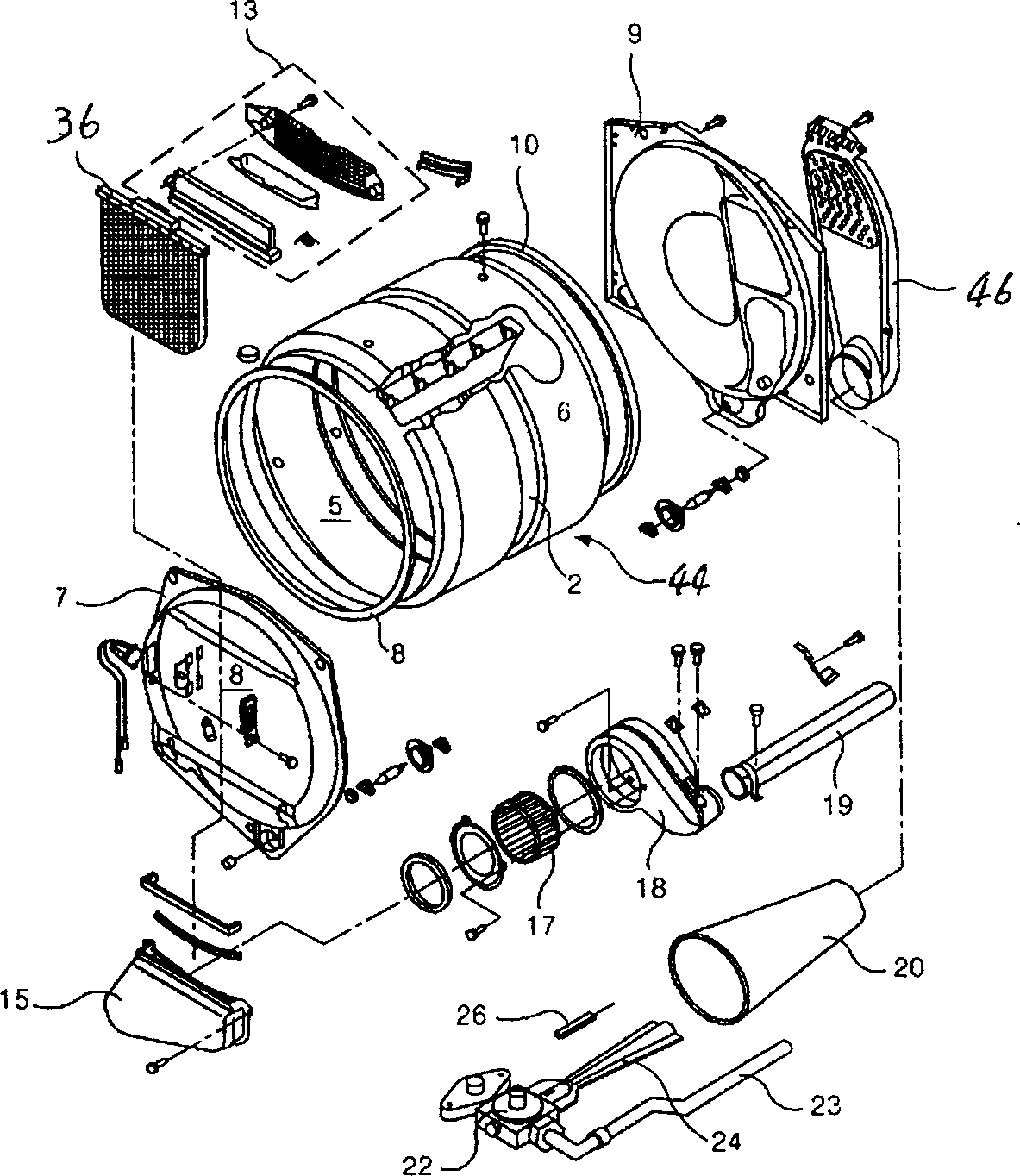
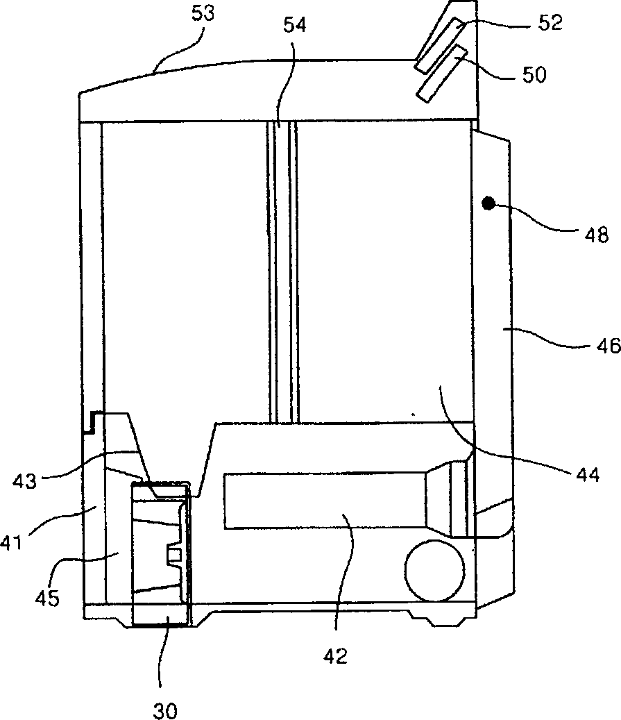
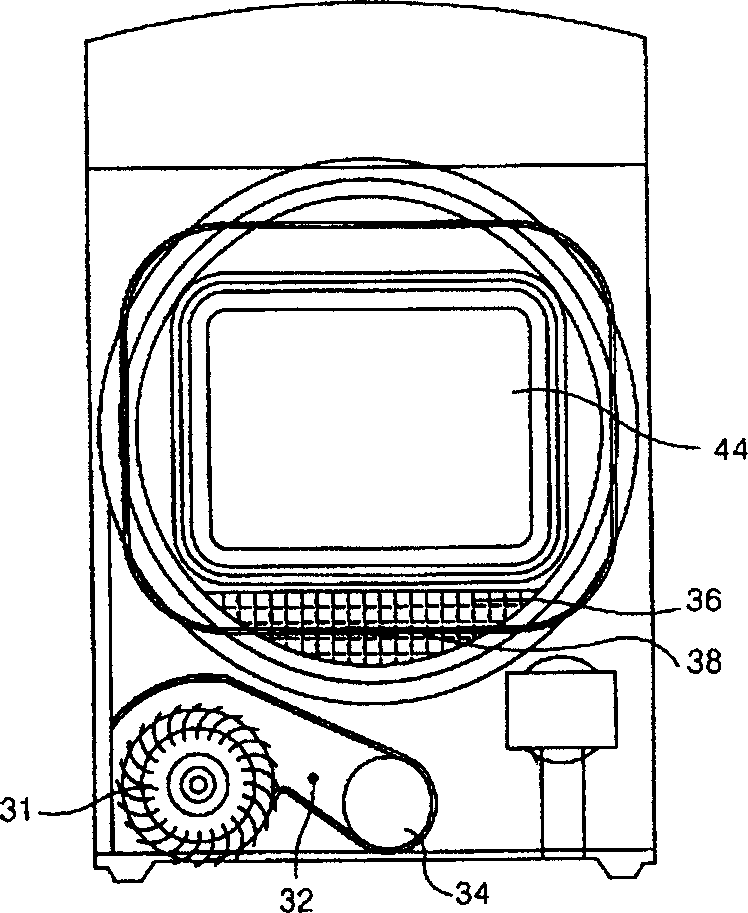
[0029] The present invention is a dryer, its structure is as shown in the figure, and the outer box body 53 is the shell of the dryer. The front panel 41 of the dryer is located at the front end of the outer box 53 . There is a rotatable drum 44 inside the outer box 53 , and the drum 44 dries the laundry put into the drum 44 . The drum 44 is rotated by a drum drive belt 54 which wraps around the outside of the drum 44 .

[0030] An exhaust port 43 is formed on the inner surface of the front panel 41 , and the exhaust port 43 opens to the inside of the drum 44 . The function of the exhaust port 43 is to discharge the air inside the drum 44 to the outside of the drum 44 . A gauze filter 36 is installed at the entrance of the exhaust port 43, and the gauze filter 36 filters foreign matter in the air.

[0031] An electrode sensor 38 is installed on...


PUM


Abstract

A baker features structurally that a mainboard for controlling baker and a switch board for controlling the driver of drum. Its control method includes such steps as monitoring the rotation speed of controllable exhaust blower, sensing the blocking degree of gauze filter and exhaust pipe, speeding up the rotation of exhaust blower to increase the air flow in drum if the gauze filter and exhaust pipe has been blocked, and controlling the heat generated by heater to prevent the heater from being turned off due to overheat.

Description

technical field [0001] The present invention relates to the invention of the dryer, and in particular to the invention of the control method for the drying time and temperature of the dryer. Background technique [0002] Already have a dryer such as figure 1 Shown, its structure is that a drum 44 is housed inside the shell (not shown in the drawings). The drum 44 is a cylinder with both ends open, and a drum belt (not shown in the drawings) driven by a separate driving source is wound on the belt groove 2, and the belt groove 2 is in the middle of the outer peripheral surface of the drum 44. The inside of the drum 44 is the drying space 5 . There are multiple baffles 6 inside the drying space 5 , and when the drum 44 rotates, the multiple baffles turn over the dried objects in the drying space 5 . [0003] The front end and the rear end of cylinder 44 are equipped with front head 7 and back head 9 correspondingly. When the front head 7 and the rear head 9 support the fro...

Claims


Application Information

Patent Timeline
Patent Type & Authority Applications(China)
IPC IPC(8): D06F58/28
CPCY02B40/72Y02B40/00
Inventor 金相斗李淳祚
Owner LG ELECTRONICS (TIANJIN) APPLIANCES CO LTD
Why Eureka
Try Eureka