Microcombustion heater having heating surface which emits radiant heat

A micro-combustion and heater technology, which is applied to burners, gas fuel burners, combustion methods, etc., can solve the problems of expensive electric heater consumption and uneconomical heaters.

Inactive Publication Date: 2004-01-14
丸田薰 +1
View PDF0 Cites 17 Cited by
  • Summary
  • Abstract
  • Description
  • Claims
  • Application Information

AI Technical Summary

Problems solved by technology

[0016] As mentioned above, the small heaters usually used to heat semiconductors are electric heaters, and electric heaters consume expensive electrical energy that is converted into heat energy
Therefore, such heaters are uneconomical

Method used


Image

  • Microcombustion heater having heating surface which emits radiant heat
  • Microcombustion heater having heating surface which emits radiant heat
  • Microcombustion heater having heating surface which emits radiant heat

Examples


Embodiment Construction

[0034] Hereinafter, embodiments according to the present invention will be described with reference to the drawings.

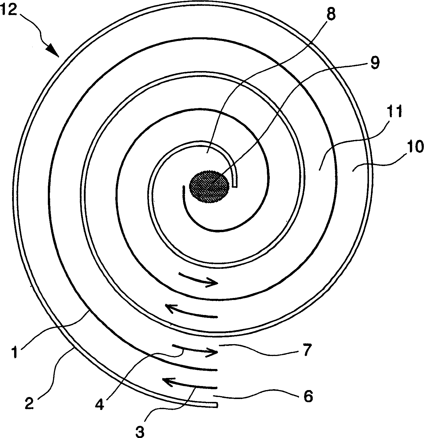
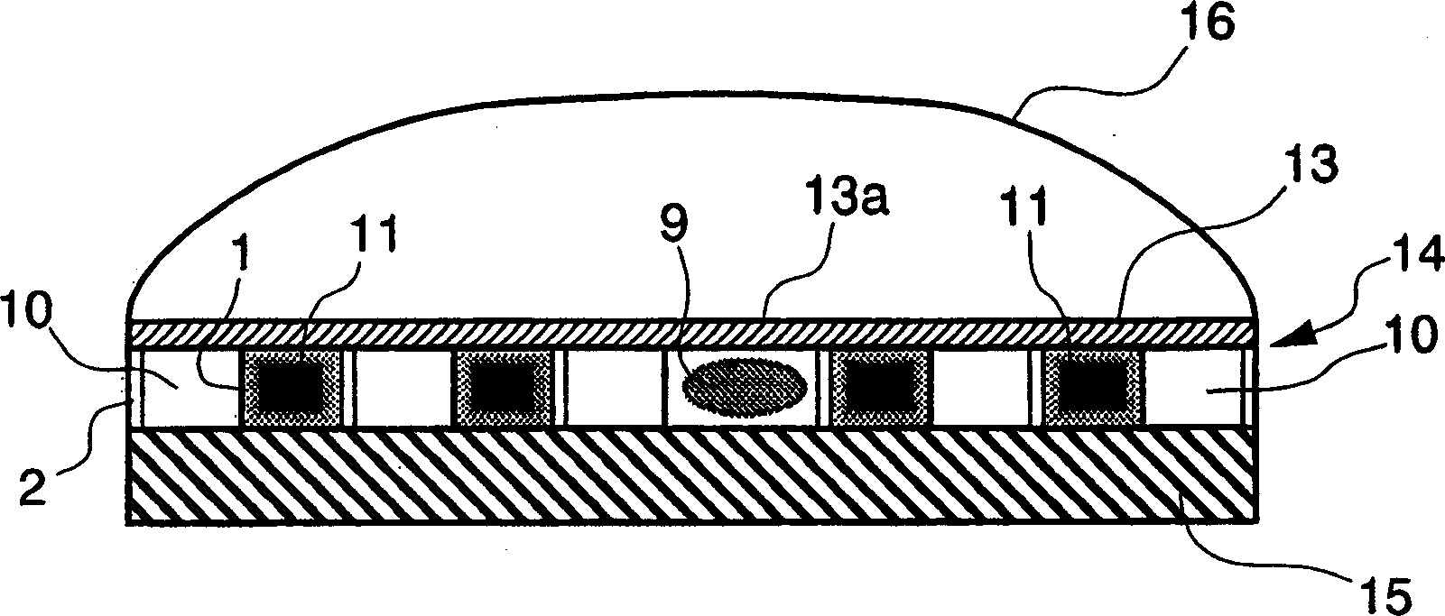
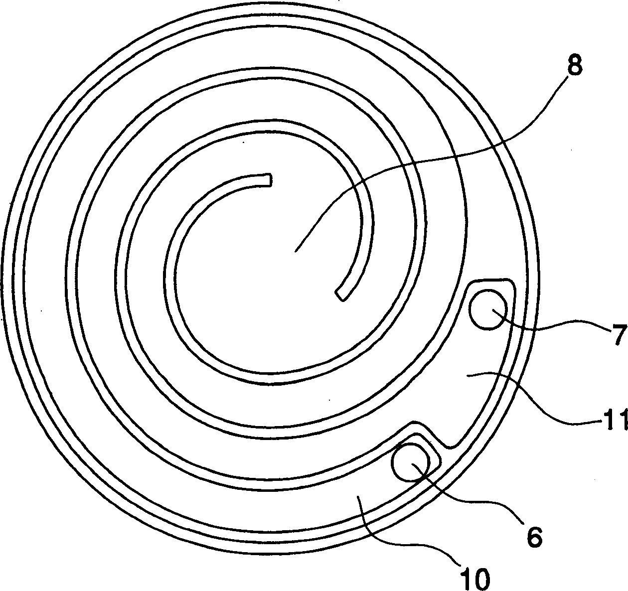
[0035] Figure 1A and 1B It is a configuration diagram showing a micro-combustion heater as an embodiment of the present invention. Figure 1A is a cross-sectional view in a plane parallel to the heating surface (explained below), Figure 1B is a cross-sectional view along the centerline. In these figures, corresponding to the above Figure 5A and 5B The same reference numerals are used for the same parts, and the same explanations will be simplified or omitted.

[0036] exist Figure 1A and 1B In , reference numeral 1 denotes a heating wall, and reference numeral 2 denotes an insulating wall.

[0037] As shown in the figure, a channel 10 for the premixed gas of air and gas drawn into the combustion chamber 8 and a channel 11 for the gas sucked out of the combustion chamber 8 to heat the wall 1 is arranged between the channels 10 and 11 way to form. T...


PUM


Abstract

A small microcombustion heater which can realize reliable combustion. The heater has a premixed gas passage which reaches a combustion chamber, and a passage for a combustion gas drawn from the combustion chamber. The passages are arranged in a spiral form in a manner such that a heating wall is provided between the passages. The width of the premixed gas passage is a quenching distance or less, where the quenching distance is determined depending on the premixed gas. The heater has two outer faces for holding the spiral passages from both sides of the upper and lower edges of the heating wall, and at least one of the outer faces is a heating surface for emitting radiant heat. Typically, the spiral passages are placed between a heat-resisting heating plate and a heat insulating plate, and an outer face of the heat-resisting heating plate functions as the heating surface.

Description

technical field [0001] The present invention relates to a micro-combustion heater with a diameter of 1 to several centimeters. Background technique [0002] In order to produce semiconductors, etc., in the process of heating an object contained in a glass tube, the glass tube is surrounded by several small heaters to form a suitable disk-shaped heater, and the heating rate of each small heater is controlled to control The temperature distribution of the heated object. [0003] If such a small heater is a combustion type (ie, a combustion heater), it is generally difficult to achieve stable combustion. Therefore, small electric heaters are used in the manufacture of semiconductors. [0004] On the other hand, small heaters known as Swiss-rolls are known and are described below: [0005] Figure 5A It is a structural diagram showing a one-dimensional counter-flow combustion heat exchanger. In the drawings, reference numeral 1 denotes a heating wall, and reference numeral 2...

Claims


Application Information

Patent Timeline
Patent Type & Authority Applications(China)
IPC IPC(8): F23D14/00F23D14/02F23D14/12F23D14/62F23D14/66
CPCF23D14/62F23D14/66F23D14/125Y02E20/34F23D14/00
Inventor 丸田薰藤森俊郎
Owner 丸田薰
Why Eureka
Try Eureka