Optical disk apparatus

A technology for optical discs and equipment, applied in the field of optical disc equipment, can solve problems such as poor structural balance, increased stroke of the optical head actuator, and poor point track

Inactive Publication Date: 2004-01-14
KK TOSHIBA
View PDF1 Cites 1 Cited by
  • Summary
  • Abstract
  • Description
  • Claims
  • Application Information

AI Technical Summary

Problems solved by technology

Therefore, there is a problem that the structural balance is poor, the stroke of the light head actuator increases during adjustment, the balance between the left and right sides is poor relative to the dot track, and errors are prone to occur

Method used


Image

  • Optical disk apparatus
  • Optical disk apparatus
  • Optical disk apparatus

Examples


Embodiment Construction

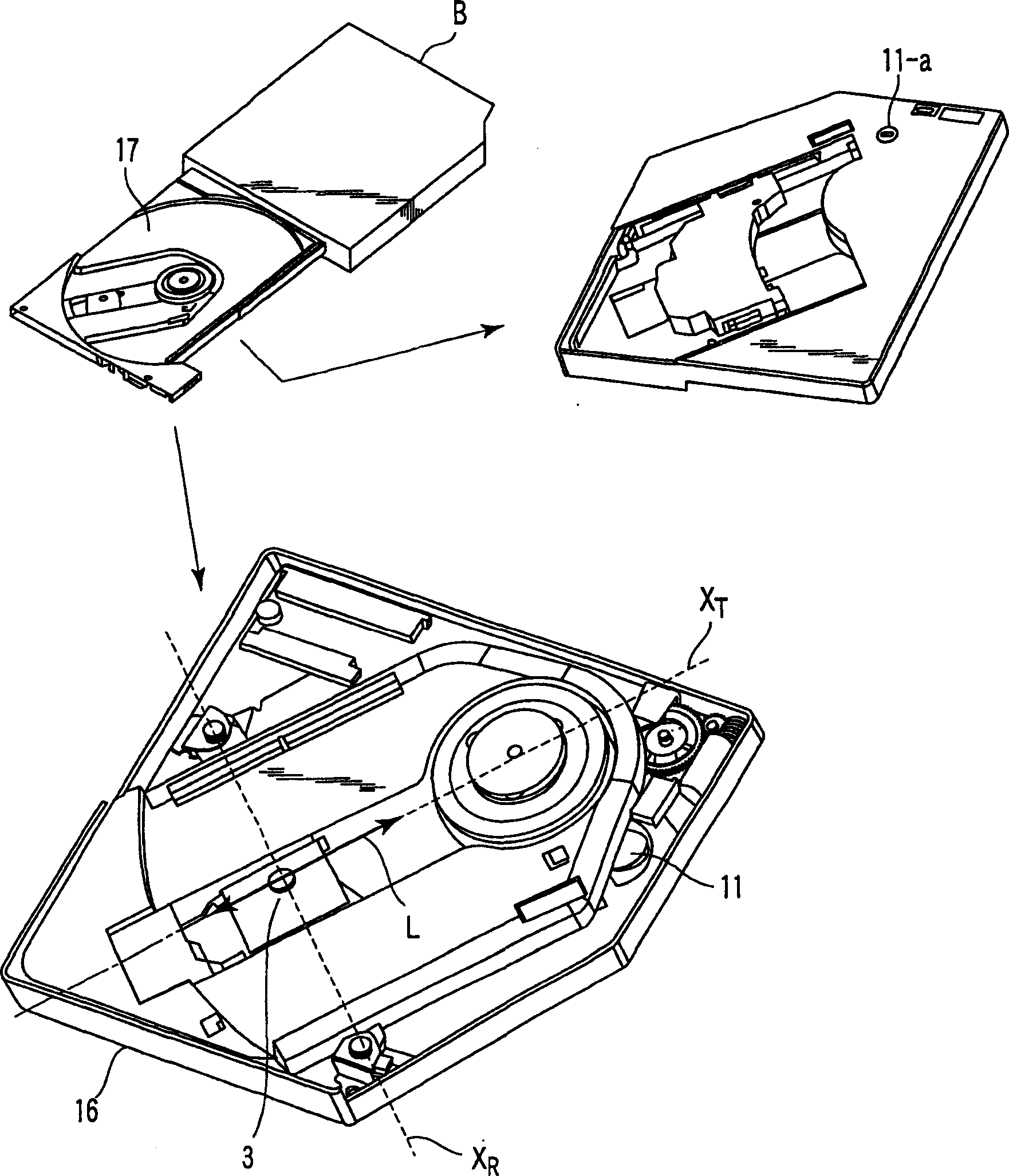
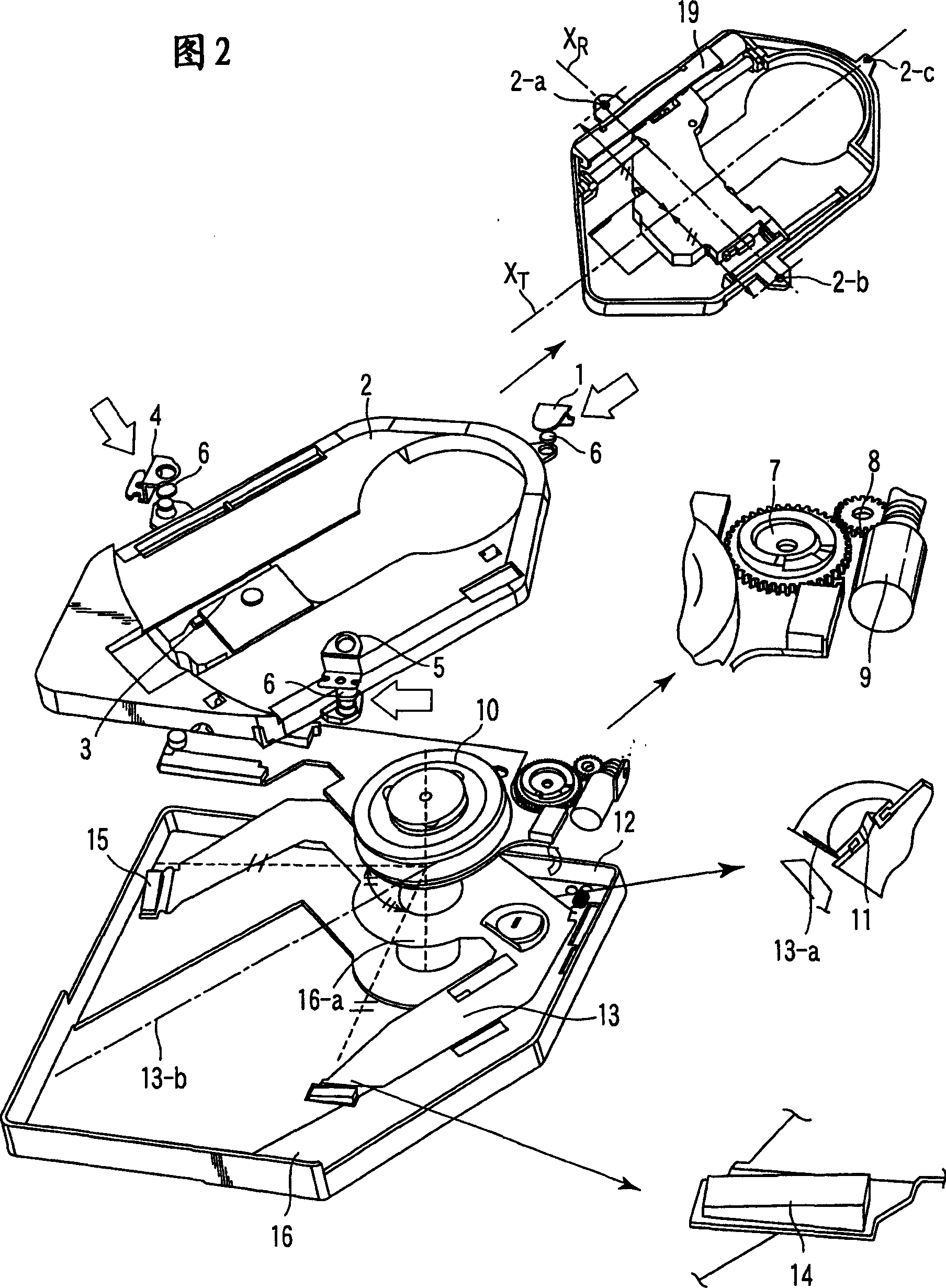
[0015] An optical disc device according to an embodiment of the present invention will be described in detail below with reference to the accompanying drawings. figure 1 is a perspective view of a cabinet, a drawer, and a main chassis of an optical disc device according to an embodiment of the present invention, and FIG. 2 is a main chassis, a sub-chassis, and several components of an optical disc according to an embodiment of the present invention exploded view of the parts. (Skew adjustment mechanism)

[0016] exist figure 1 In and 2, according to an embodiment of the present invention, the optical disc drive device has a drawer 17, a main chassis 16 and a sub-chassis 2 in order from the casing B, in which a CD is stored in the above-mentioned casing, and the main chassis 16 and the sub-chassis 2 is included in said drawer 17. in addition, figure 1 A keyway portion 11a of the adjustment cam in the tangential direction is shown, said keyway portion 11a being introduced in...


PUM


Abstract

An optical disk apparatus includes a main chassis and a sub-chassis provided on a drawer, and has a skew adjusting mechanism of the main chassis and the sub-chassis which is skew-adjusted with reference to a rotational axis in tangential direction XT, which is parallel to a spot trajectory L of an optical pickup and located in the vicinity of the spot trajectory L, and a rotational axis in radial direction XR perpendicular to the rotational axis in tangential direction XT. This enables the skew adjustment in which a change in height of the optical pickup is small during the adjustment and distortion is small.

Description

technical field [0001] The present invention relates to an optical disc device, in particular to an optical disc device with a main chassis and a sub-chassis deflection adjustment mechanism. The main chassis and the sub-chassis store an optical pick-up mechanism and an optical disc motor. Background technique [0002] While optical disc devices are becoming more and more popular, miniaturization and high performance are recently required for the optical disc device as a whole. Therefore, mechanically high precision is also required in the structure of the optical disc device. For example, compatibility between miniaturization and high precision is desired in a skew adjustment mechanism of a main chassis and a sub-chassis which store an optical pickup mechanism and a disc motor. [0003] In Japanese Patent Application Laid-Open No. 2001-60323, a skew adjustment mechanism between the main chassis and sub-chassis is disclosed, wherein the skew adjustment is referenced to one r...

Claims


Application Information

Patent Timeline
Patent Type & Authority Applications(China)
IPC IPC(8): G11B7/08G11B7/085G11B7/095G11B17/028G11B19/20G11B21/16
CPCG11B19/2009G11B21/16G11B7/082G11B17/028G11B7/08582
Inventor 江口直纪
Owner KK TOSHIBA
Why Eureka
Try Eureka