
Electric cable connector

A cable connection and connector technology, which is applied in the direction of connection, two-part connection device, and parts of the connection device, etc., can solve problems such as difficulty in wiring

Inactive Publication Date: 2004-01-21
SUMITOMO WIRING SYST LTD
View PDF0 Cites 5 Cited by
  • Summary
  • Abstract
  • Description
  • Claims
  • Application Information

AI Technical Summary

Problems solved by technology

Therefore, wiring in tight spaces will be difficult

Method used


Image

  • Electric cable connector
  • Electric cable connector
  • Electric cable connector

Examples


Embodiment Construction

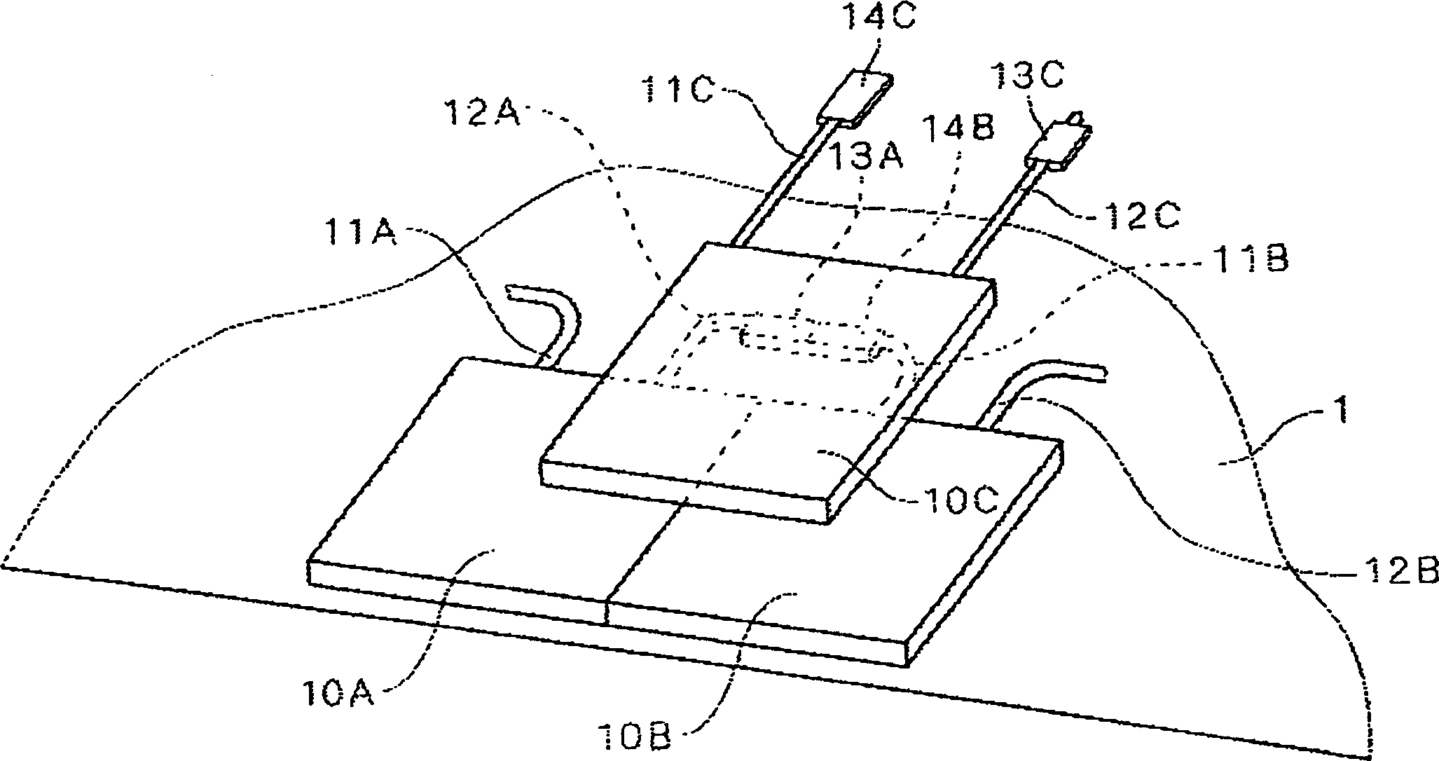
[0023] figure 1 is a perspective view schematically showing a component of a solar power generation system integrated with building materials, such as a solar power generation system integrated into roof tiles, which adopts a solar power generation system according to the present invention Exemplary embodiment cable connector structures. Such as figure 1 As shown, solar cell modules 10A, 10B, and 10C integrated with roof tiles are arranged on a substrate, such as a roof slab 1, which is used as a base for shingles or other items on the roof. The solar cell modules 10A to 10C are manufactured by embedding solar cells in building materials such as thick roof slates. The solar cell modules 10A to 10C can be installed in a desired pattern by laying roof tiles, such as any existing laying method or a later developed laying method.

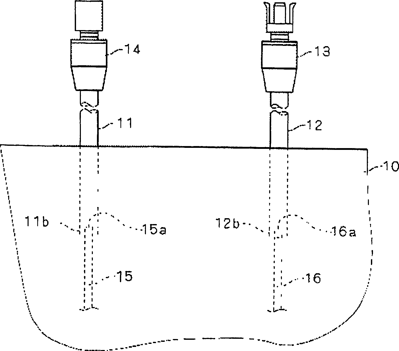
[0024] Preferably, the solar cell modules 10A, 10B, and 10C are directly connected to the positive cables 11A, 11B, 11C and the negative cables 12...


PUM


Abstract

A cable connector is provided that can accomplish routing of cables in a narrow space in connecting solar cell modules to each other. A plurality of solar cell modules having solar cells embedded in a building material are installed on a base board. A positive cable and a negative cable extend from the solar cell module. A first connector is connected to a an end of one cable. A second connector is connected to an end of the other cable. The first connector and the second connector have a flat outer configuration and are connected to each other, with a thickness direction of the first connector and that of the second connector substantially coincident with each other. Each of the first connector and the second connector is connected to the respective flat cable with a thickness direction of the connector substantially coincident with that of the flat cable.

Description

technical field [0001] The invention relates to a cable connector. More specifically, the present invention relates to such a cable connector: it is used to electrically connect a plurality of modules through cables, wherein the modules are, for example, solar battery modules. Background technique [0002] The solar power generation system that can convert sunlight into electrical energy will not pollute the earth's environment and can save energy, so the public is optimistic about such a system. In a solar power generation system, in order to make the power output sufficient to achieve the required power, dozens or hundreds of solar cell modules are arranged side by side, and these solar cell modules are connected in series with cables. A conventional practice is to install a large number of solar cell modules on the roof after the building is completed. However, in recent years, in order to simplify the assembly process and reduce the construction cost, building material...

Claims


Application Information

Patent Timeline
Patent Type & Authority Applications(China)
IPC IPC(8): E04D1/30H01L31/042H01R13/627
CPCH01R13/6271Y10S439/928Y02B10/12H02S40/36Y02E10/50Y02B10/10
Inventor 吉川裕之东小薗诚
Owner SUMITOMO WIRING SYST LTD
Learn More