Connector for card

A technology of connecting device and mounting part, which is applied to the parts, connection, coupling device and other directions of the connecting device, can solve the problems such as the increase in the number of parts, the bulky electronic equipment, and the low working efficiency of the second card member.

Inactive Publication Date: 2004-02-18
ALPS ALPINE CO LTD
View PDF1 Cites 3 Cited by
  • Summary
  • Abstract
  • Description
  • Claims
  • Application Information

AI Technical Summary

Problems solved by technology

[0008] The problem with the above-mentioned conventional card connectors is that if different types of card connectors are prepared corresponding to the types of card members with different sizes, the electronic equipment to which the card connectors are installed will be very bulky.
[0010] However, this card connecting device capable of mounting two types of card members has a problem in that an auxiliary member is required to temporarily fix the second card member, which increases the number of parts.
In addition, the second card member must be temporarily fixed on the auxiliary member, and then installed on the card installation part, and the work efficiency when installing the second card member is low

Method used


Image

  • Connector for card
  • Connector for card
  • Connector for card

Examples


Embodiment Construction

[0091] Embodiment of the invention

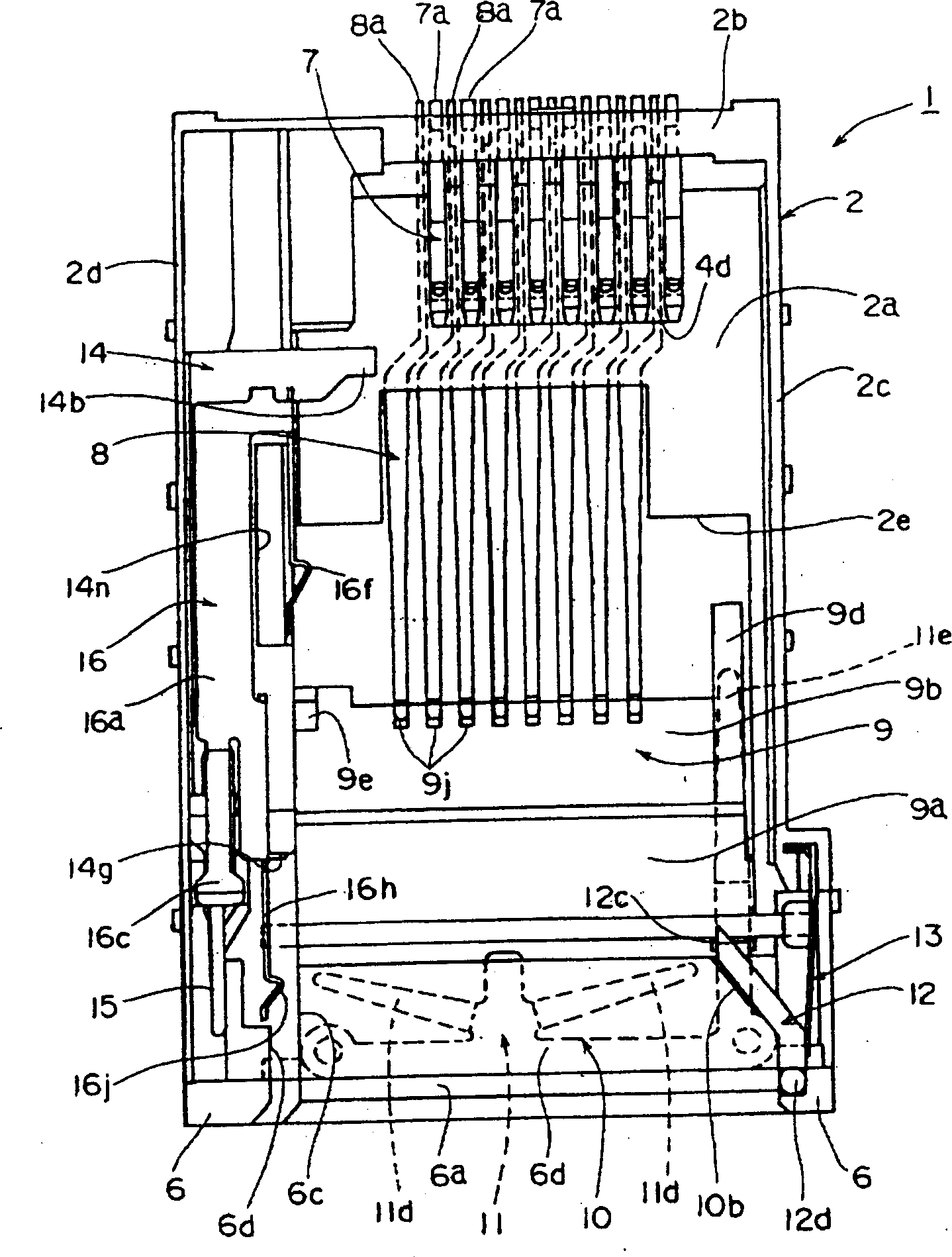
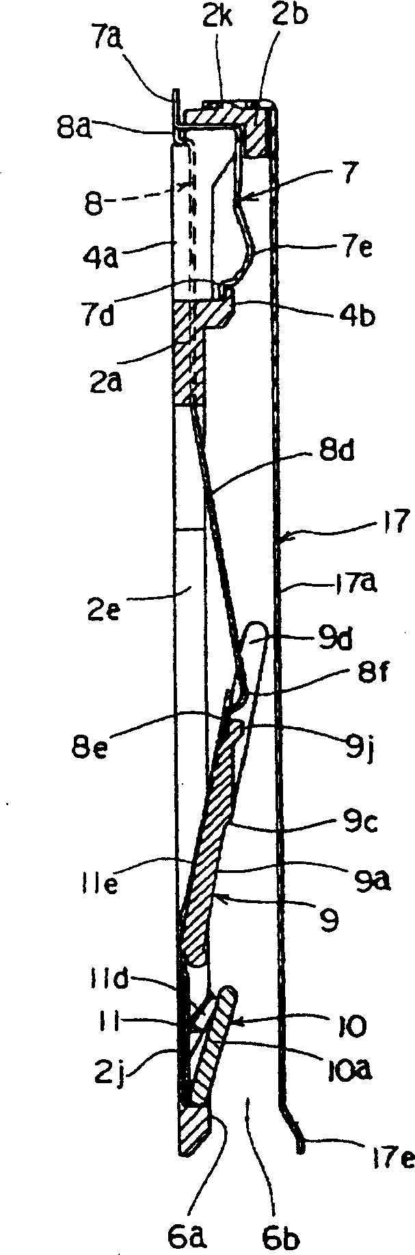
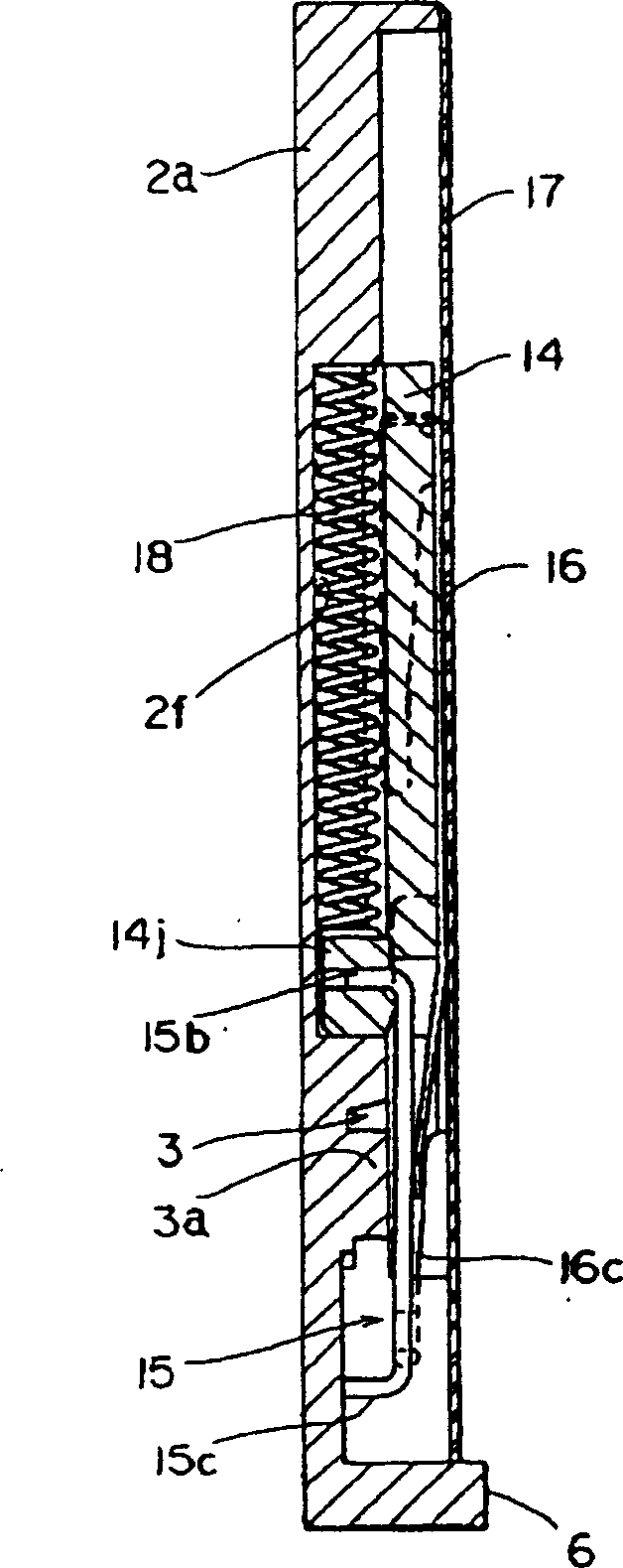
[0092] based on the following Figure 1 to Figure 6 0, the card connection device according to the embodiment of the present invention will be described in detail.

[0093] Figure 1 ~ Figure 3 It is a figure explaining the structure of the card connection apparatus of this invention. Figure 4 ~ Figure 11 It is a figure explaining the case concerning this invention. Figure 12 to Figure 14 It is a figure explaining the 1st terminal member concerning this invention. Figure 15 ~ Figure 17 It is a figure explaining the 2nd terminal member concerning this invention. Figure 18 ~ Figure 21 It is a figure explaining the 1st guide member concerning this invention. Figure 22 ~ Figure 23 It is a figure explaining the 2nd guide member concerning this invention. Figure 24~ Figure 26 It is a figure explaining the 1st elastic member concerning this invention. Figure 27 ~ Figure 29 It is a figure explaining the 3rd guide member concerning th...


PUM


Abstract

PROBLEM TO BE SOLVED: To provide a connector device for a card which can attach two types of card members of different thickness and width in dimensions can be attached to a card attachment part even without using an auxiliary member. ŽSOLUTION: The slider of this connector device for a card is arranged slidably in the vicinity of one-side edge parts 19d and 20d of respective first and second card members 19 and 20 attached to the card attachment part. In the slider 14, a first contact part 14b is formed, on a deep side farther from a card insertion slot 6b, on which a front end part 19a side of the first card member 19 attached to the first attachment part is allowed to abut, and a second contact part 14g is formed, on this side closer to the card insertion slot 6b, on which a front end part 20a side of the second card member 20 inserted to the second attachment part is allowed to abut. The second attachment part is positionally shifted in the direction such that the first card member 19 inserted in the first attachment part is not brought into contact with the second contact part 14g. Ž

Description

technical field [0001] The present invention relates to a connection device for a card, and more particularly to a connection device for a card capable of writing to or reading from an IC card used in a storage medium such as a personal computer and a memory card used in an electronic device such as a digital camera. Background technique [0002] As an external recording device for electronic equipment such as a personal computer (hereinafter referred to as PC) and a digital camera, for example, an IC card with an IC (integrated circuit) enclosed inside, a card connection device is generally used for writing or reading various information. As a recording medium of such conventional card connectors, small card members such as PC cards and memory cards are widely used. [0003] The card connecting device capable of mounting such a card member can write or read necessary information on the card member. However, there are many newly developed varieties of small card components ...

Claims


Application Information

Patent Timeline
Patent Type & Authority Applications(China)
IPC IPC(8): B42D15/10G06K17/00H01R13/629H01R43/00
Inventor 中村英弘
Owner ALPS ALPINE CO LTD
Why Eureka
Try Eureka