Pipe body making method, pipe body and image forming device using the same

A manufacturing method and a technology for a pipe body, applied to the manufacture of the pipe body, can solve the problems of unconfirmed occurrences and increased cost, and achieve the effects of suppressing cost increase, improving strength, and preventing deformation

Inactive Publication Date: 2004-02-25
RICOH KK
View PDF1 Cites 7 Cited by
  • Summary
  • Abstract
  • Description
  • Claims
  • Application Information

AI Technical Summary

Problems solved by technology

[0006] However, the above-mentioned deformation does not necessarily occur. Even in the same batch of products, there are occasions where it is confirmed and when it is not confirmed. As mentioned above, in the case of manufacturing high-precision products, it is necessary to inspect all finished products, and there are costs additional questions

Method used


Image

  • Pipe body making method, pipe body and image forming device using the same
  • Pipe body making method, pipe body and image forming device using the same
  • Pipe body making method, pipe body and image forming device using the same

Examples


no. 1 example

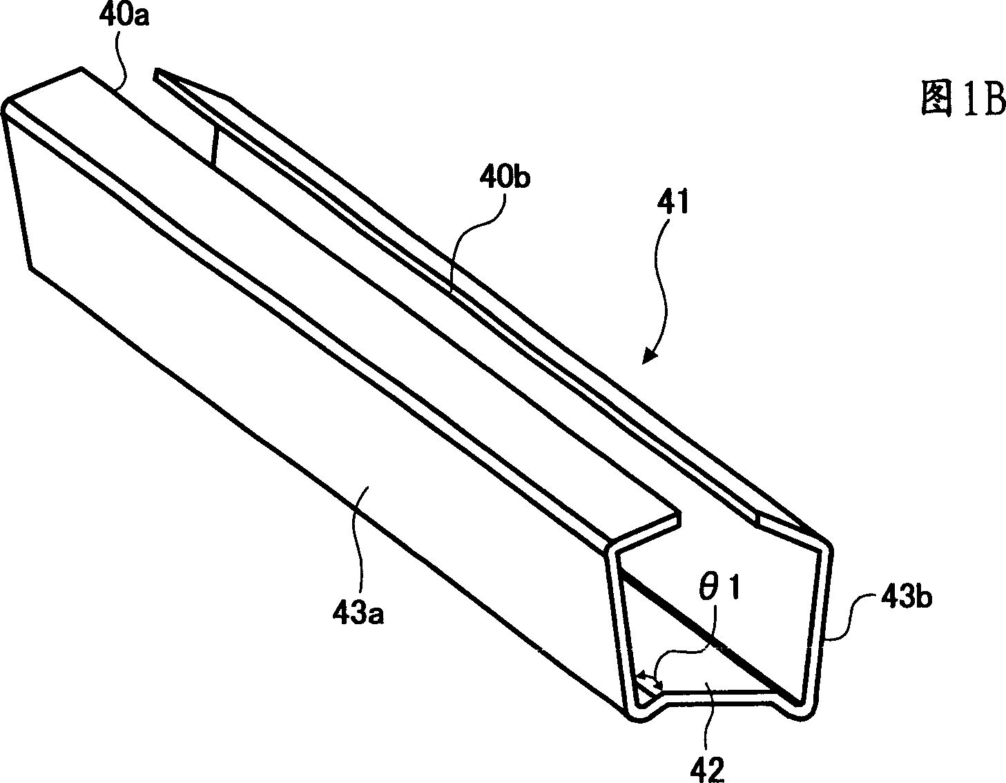
[0086] Fig. 2 is a perspective view of the pipe body involved in the first embodiment of the present invention, image 3 It is a front view showing the pipe body in FIG. 2 . Figure 2 and image 3As shown, the pipe body 1 has a rectangular cross-section, which includes a bottom wall 2, a pair of side walls 3 and 4 adjacent to the bottom wall 2, and an upper wall facing the bottom wall 2. 5, as the four faces corresponding to the sides of the rectangle. The top wall portion 5 is composed of a pair of seam wall portions 5a, 5b. The seam wall portions 5a, 5b are respectively provided with end faces 5c, 5d, and the above end faces 5c, 5d are in close contact with each other. A joint portion 5e that is a seam is formed in the center.

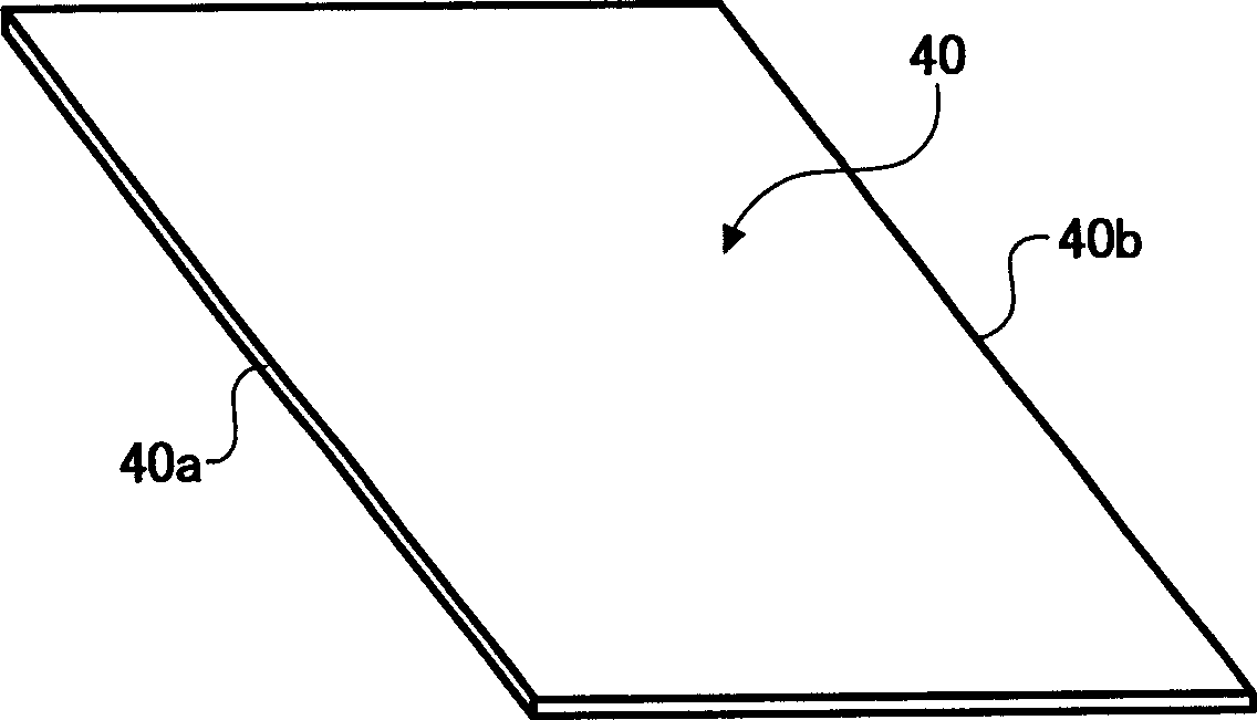
[0087] like Figure 4 As shown, the pipe body 1 is formed by pressing a rectangular metal plate 6 as a raw material. The metal plate 6 includes a pair of sides 6e, 6e parallel to each other. As the material of the above-mentioned metal plate 6, a...

no. 2 example

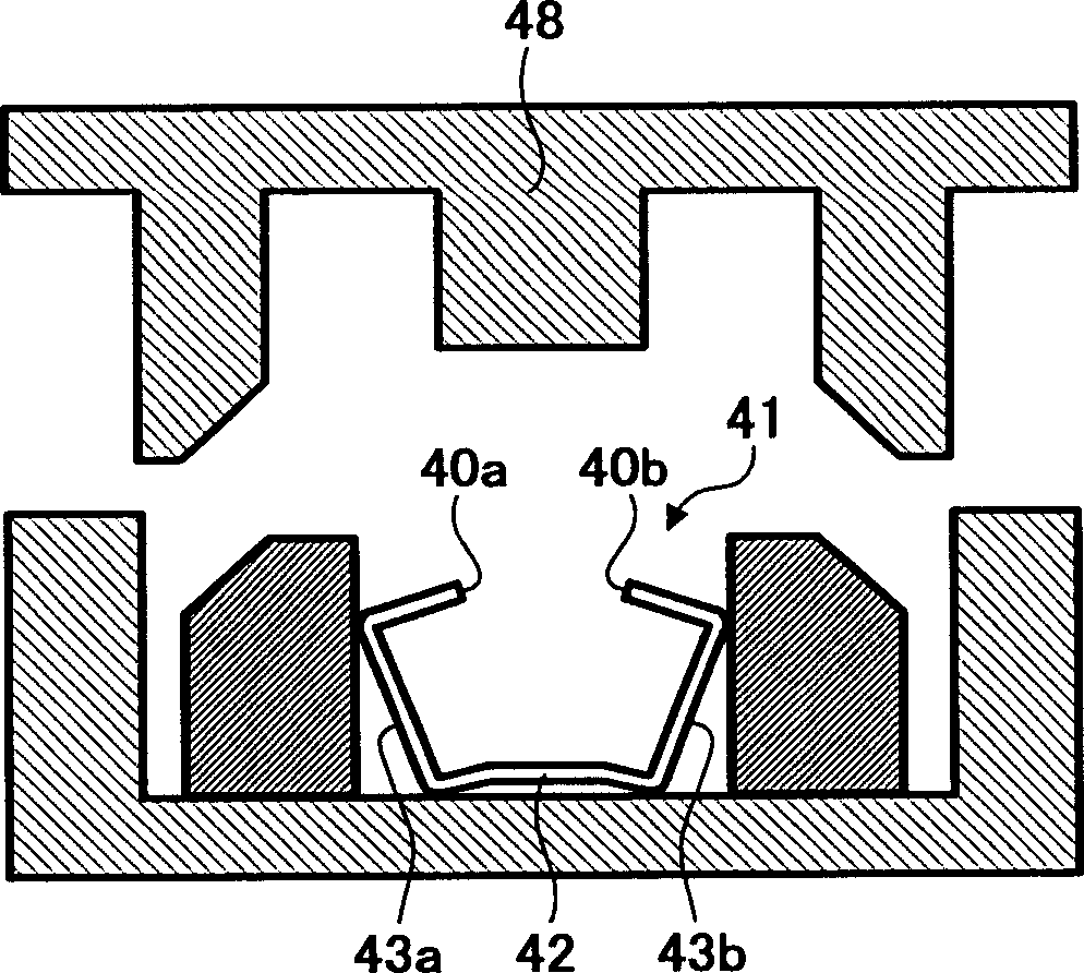
[0112] In the pipe body manufacturing method involved in this embodiment, in the third processing step, use Figure 19 In place of the pressure forming device 21, a pressure forming device 21a is shown. This pressure forming device 21a is different from the pressure forming device 21 in that it is provided with frictional contact members 27c, 27c with high friction coefficients on the punch surfaces 27b, 27b of the third pressurizing punch members 27, 27, and is different from the pressure forming device 21 in other points. One embodiment is the same, the same part is marked with the same symbol, and the description is omitted.

[0113] like Figure 19 As shown, for the secondary intermediate molded product 14 obtained through the first processing step and the second processing step, as the third processing step, it is first placed in the facing space of the third pressing punch parts 27, 27 28, so that a constituting wall 15 faces downward. If the upper die 23 is lowered f...

no. 3 example

[0120] In the pipe body manufacturing method according to the present embodiment, as shown in FIG. 25 , in the first processing step and the second processing step, the secondary intermediate molded product 14 is formed so that a constituting wall portion 15 and an adjoining surface constitute the wall portion. The angle θ4 formed by 16a, 16b = 90°. In the third processing step, instead of the pressure forming device 21, the pressure forming device 21b is used. This pressure forming device 21b is different from the pressure forming device 21 in that the protrusions 27e, 27e are provided on the punch surfaces 27b, 27b of the third pressurizing punch members 27, 27, and the other is the same as the first embodiment. The same part is marked with the same symbol, and the description is omitted.

[0121] As for the secondary intermediate molded product 14 obtained through the first processing step and the second processing step, as a third processing step, it is placed in the cent...


PUM


Abstract

The present invention relates to a tube body manufacturing method, a tube body, and an image forming apparatus using the tube body. In the pipe body manufacturing method according to the present invention, an external force is applied to the wall portion (16a, 16b) on the adjacent surface of the secondary intermediate molded product (14), so that the pair of sides (6e, 6e) are in close contact with each other, and the remaining The resilient force in the close contact state produces a pipe body, and in the processing step of forming the secondary intermediate molded product (14), a plastic deformation portion (6f) is formed on the adjacent surface constituting wall portion (16a, 16b). The portion (6f) extends in a direction perpendicular to the bending line of the metal plate. During press processing, the external force is absorbed by the plastic deformation part, which can prevent the deformation of the surface formed by the wall part formed by the adjacent surface of the pipe body. Conduct inspections to curb rising costs.

Description

technical field [0001] The present invention relates to a pipe body manufacturing method, the pipe body, and an image forming apparatus using the pipe body. More specifically, the present invention relates to manufacturing a pipe body having a rectangular cross section by bending a metal plate. Background technique [0002] As a prior art for producing a pipe body having a rectangular cross section, Japanese Patent Application Laid-Open No. 2001-286934 already proposed by the present applicant can be cited. In this bulletin, as Figure 1A As shown, the metal plate 40 includes a pair of sides 40a, 40b parallel to each other, and is formed into an intermediate formed product 41 as shown in FIG. 1B by bending the metal plate. The intermediate molded product 41 includes three constituent wall portions 42, 43a, 43b, and the central constituent wall portion 42 forms an obtuse angle θ1 with the adjacent face constituent wall portions 43a, 43b respectively (only the constituent wall...

Claims


Application Information

Patent Timeline
Patent Type & Authority Applications(China)
IPC IPC(8): B21C37/15B21D5/01B21D22/02B21D51/16
CPCB21D5/015
Inventor 前田大树近藤崇史
Owner RICOH KK
Why Eureka
Try Eureka