Vehicle eddy current brake experiment unit

An experimental device, eddy current braking technology, applied to vehicle components, electric braking systems, electric vehicles, etc., can solve problems such as inability to simulate operating modes

Inactive Publication Date: 2004-02-25
TONGJI UNIV +1
View PDF0 Cites 8 Cited by
  • Summary
  • Abstract
  • Description
  • Claims
  • Application Information

AI Technical Summary

Problems solved by technology

Similar foreign eddy current braking experimental systems have a rotating test bench with a running speed greater than 300km / h, but the eddy current braking poles are fixedly installed.
None of them can simulate the unique operation mode of the eddy current braking device of TR series maglev trains

Method used


Image

  • Vehicle eddy current brake experiment unit
  • Vehicle eddy current brake experiment unit
  • Vehicle eddy current brake experiment unit

Examples


Embodiment Construction

[0026] The present invention is further described below by way of examples.

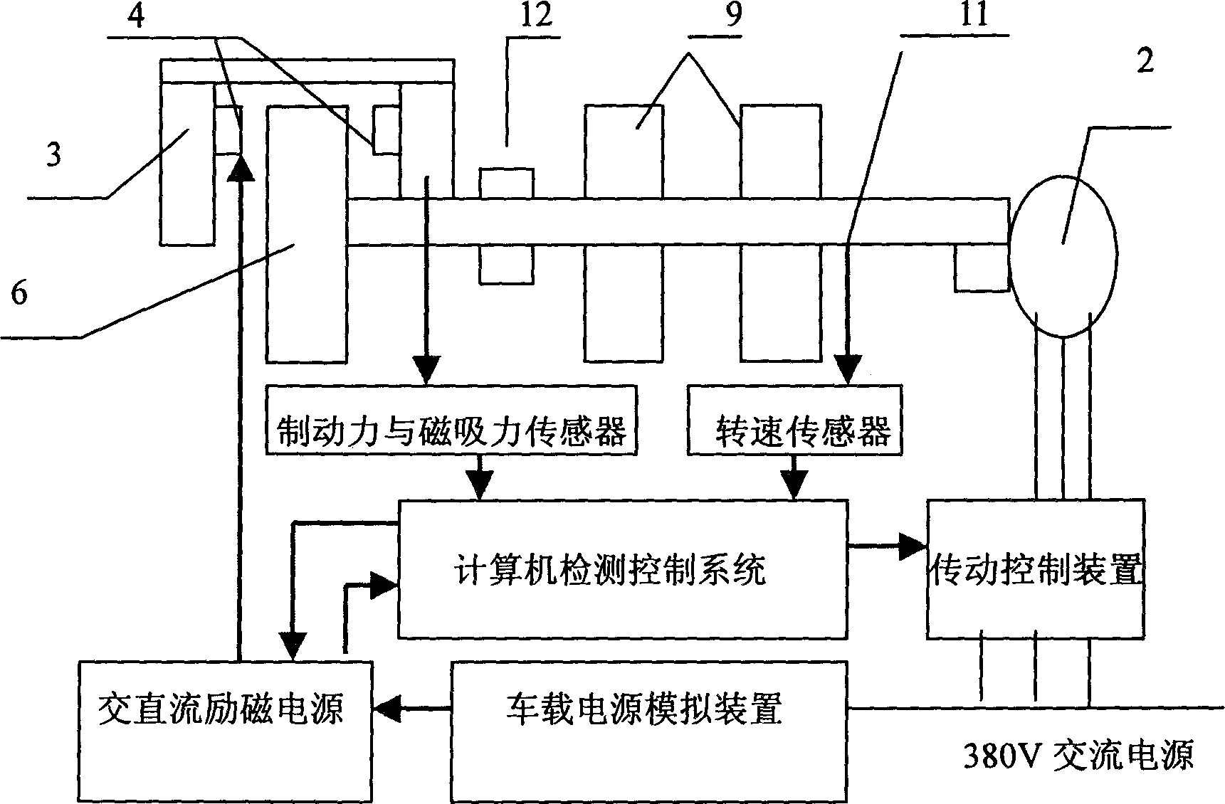
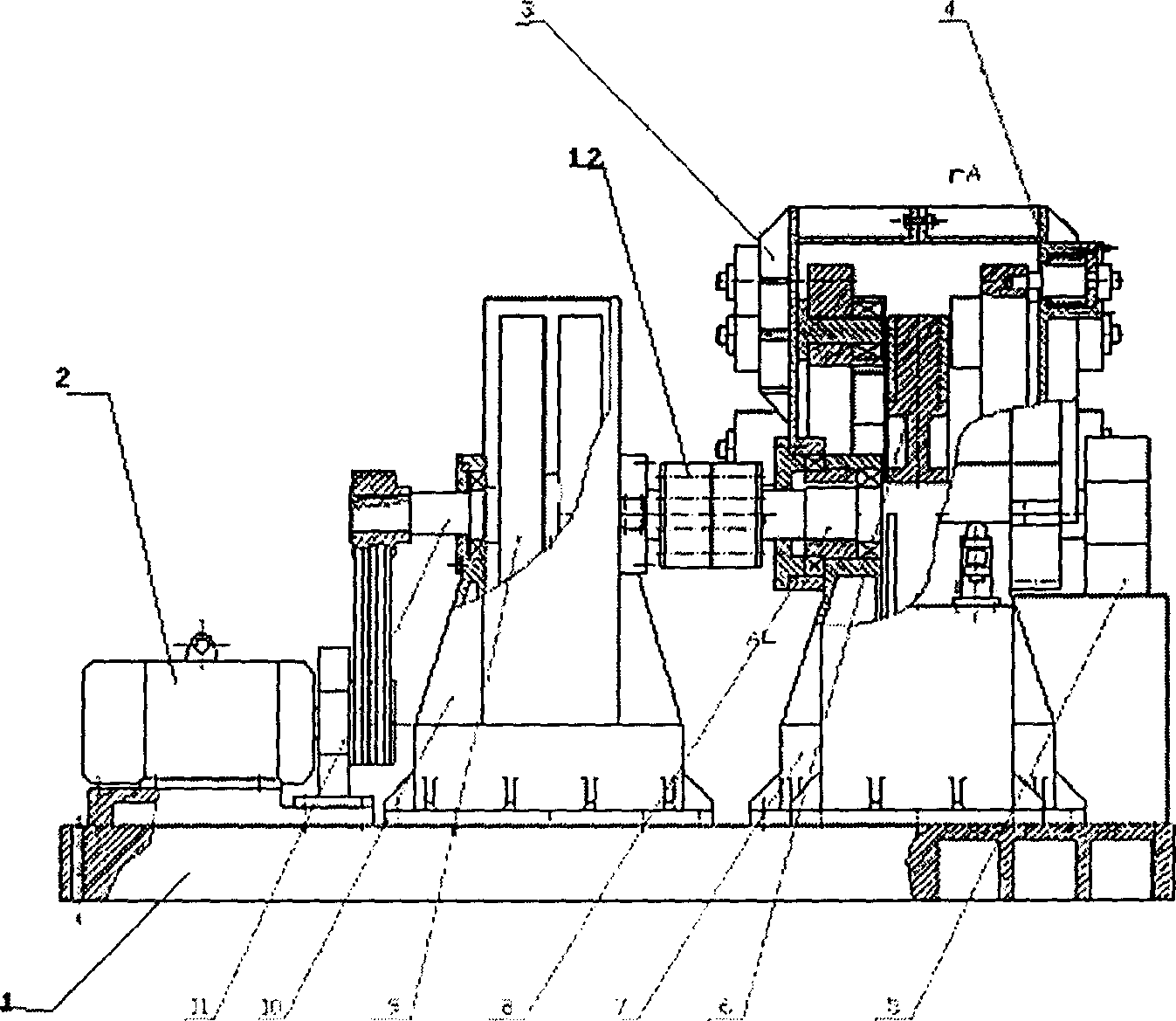
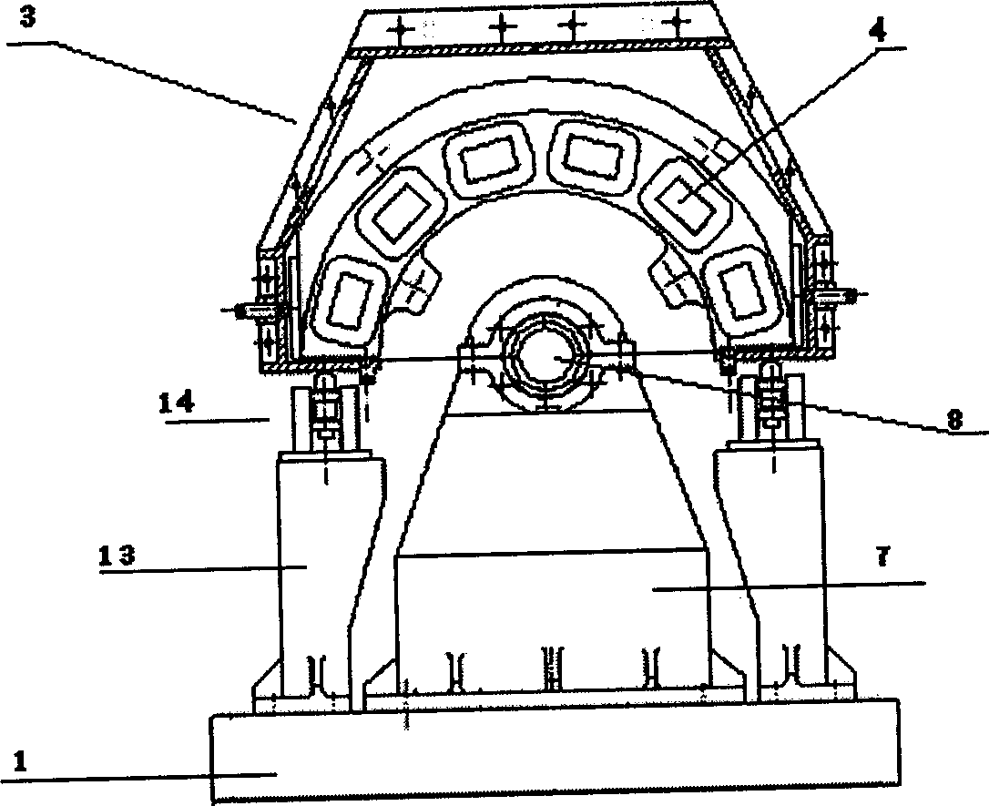
[0027] In the embodiment, the track test wheel has a diameter of 1380 mm and a thickness of 200 mm; the inertia wheel has a diameter of 1215 mm and a thickness of 150 mm. The speed is about 1470 rpm, and the outer edge speed of the track wheel test is 350km / h. The track wheel test consists of a wheel body and an induction board (a guide rail simulation board on a maglev line). 12 magnetic poles, 12 damping springs, and 10 magnetic attraction sensors are installed on the magnetic pole installation support device 3 . There are also four brake force sensors.

[0028] Maximum moment of inertia: ∑J 实际 =J 轨道轮 +2J 惯性轮 +J 零 =934.34N·m·s 2 . The size of the magnetic pole core is 190 x 250 x 90 mm long; the magnet winding is 350 turns, and the ampere-turns are 110 x 350 x 2 x 6. Dimensions of each electromagnet: 260mm×204mm; iron core 90×150mm. The maximum vertical magnetic attraction is greater than...


PUM


Abstract

The eddy-current brake experiment equipment for high-speed track traffic system includes base seat, rotary track, electromagnetic equipment, field power supply, vehicle power supply simulator, computer measurement and control device and driving device. When the rotary track is rotated at high speed, by means of action of field power supply the multipoint distributed measuring sensor can be used for detecting the action state of eddy-current brake and electromagnetic attraction so as to obtain the working state of eddy-current brake.

Description

technical field [0001] The invention belongs to the field of electromechanical technology, and in particular relates to an eddy current braking experimental device for a high-speed rail transit system. Background technique [0002] With the development of urban high-speed rail transit system (including maglev transportation system and wheel-rail high-speed system), safety control technology is one of the technologies that must be considered and solved first. [0003] At present, the world's first commercially operating maglev line introduced by Shanghai is the TR08 high-speed maglev train imported from Germany. The key part of the safety control device loaded on this car is the eddy current braking device. [0004] How to verify the effectiveness of the principle of eddy current braking technology, verify the feasibility of eddy current braking equipment manufacturing technology, verify the availability and reliability of vehicle-mounted equipment, and verify the availabili...

Claims


Application Information

Patent Timeline
Patent Type & Authority Applications(China)
IPC IPC(8): B60L7/28
Inventor 郭其一朱龙驹朱仙福刘进华应之丁艾正武
Owner TONGJI UNIV
Why Eureka
Try Eureka