Suspension arrangement

A technology of suspension device and driving device, which is applied in the direction of suspension, elastic suspension, transportation and packaging, etc.

Inactive Publication Date: 2004-02-25
GIBBS TECH
View PDF3 Cites 17 Cited by
  • Summary
  • Abstract
  • Description
  • Claims
  • Application Information

AI Technical Summary

Problems solved by technology

Similarly, U.S. Patent No. 5,755,173 (Rorabaugh and Costa) discloses the use of a transverse screw jack through the center of the vehicle adjacent the front and rear axles, but this also creates packaging issues

Method used


Image

  • Suspension arrangement
  • Suspension arrangement
  • Suspension arrangement

Examples


Embodiment Construction

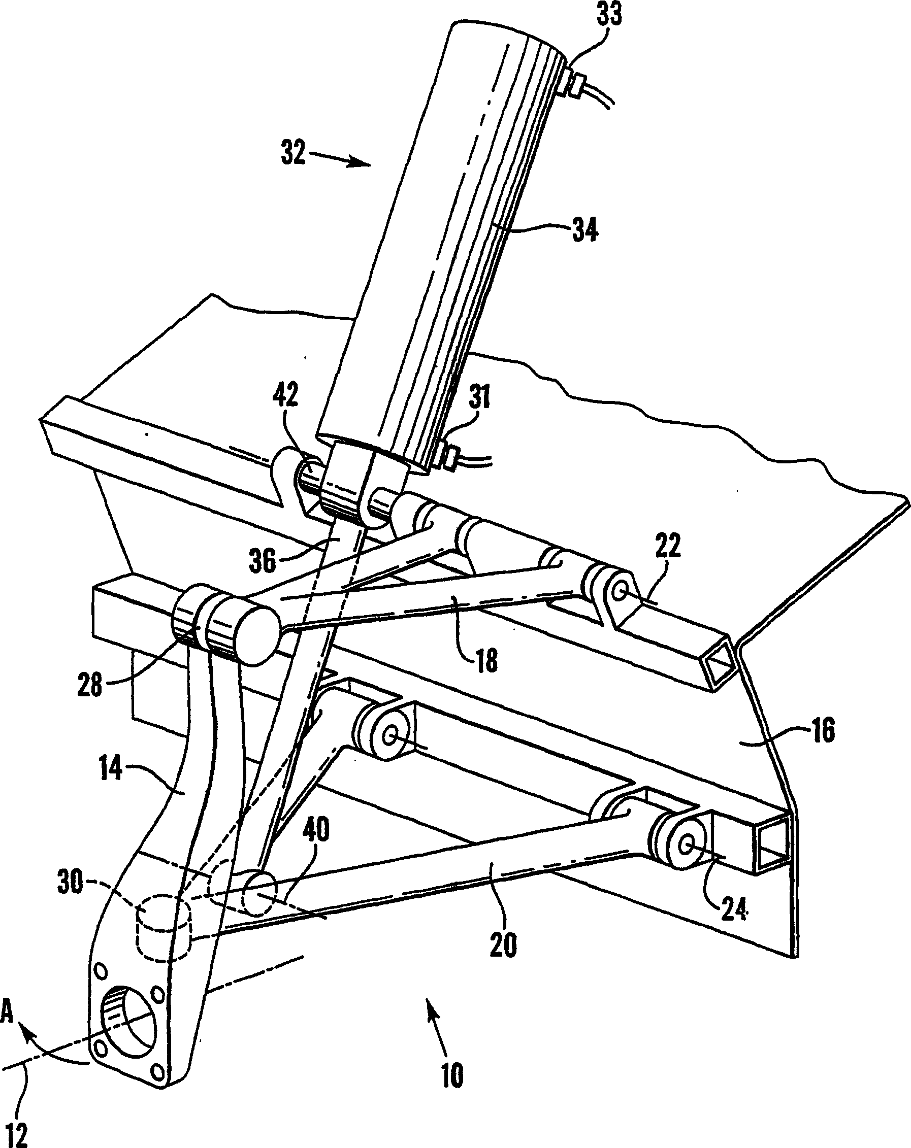
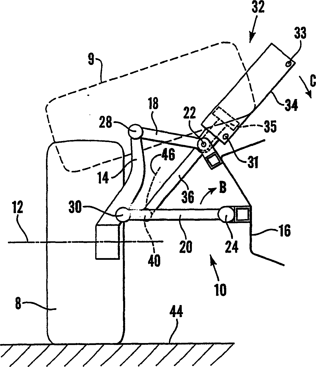
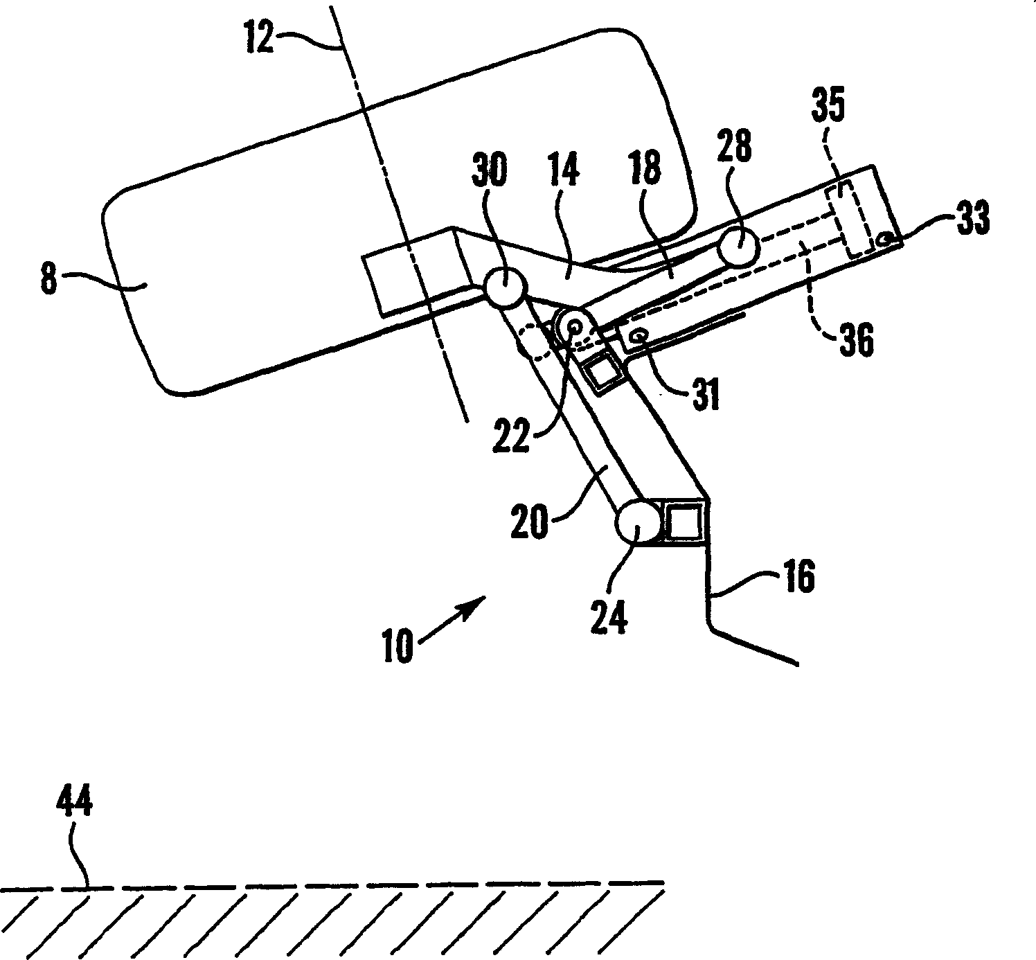
[0019] First refer to figure 1 and figure 2 , the suspension arrangement for the amphibious wheel 8 is indicated generally by reference numeral 10 . The wheels 8 are mounted for rotation about an axis 12 on axles (not shown), which are typically fixed to vertical wheel supports 14 . Upper control arms 18 and lower control arms 20 support vertical wheel supports 14 from vehicle body 16 . The control arms 18 , 20 are arranged in-line at a distance from each other and are rotatably fixed to the vehicle body 16 about respective parallel axes 22 , 24 . This is what is commonly referred to as a double-wishbone suspension arrangement.

[0020] Respective ball joints 28 , 30 connect the control arms 18 , 20 to the vertical wheel supports 14 . The ball joint enables a steering movement of the vertical wheel support 14 so that the wheel 8 in the lateral plane can be steered in drive mode as indicated by arrow A. The ball joints 28, 30 also cause the control arms 18, 20 to move tog...


PUM


Abstract

Vehicle suspension (10) comprises control arm (20) pivotally mounted to vehicle body (16) at (24). Wheel support (14) is pivotally mounted to the control arm. Drive means (32), in this case a hydraulic strut (34), is pivotally mounted to body (16) at trunnion mount (42). The wheel may be protracted to be placed vertically on the road surface (44), or retracted at an angle, for example to allow good marine performance in an amphibious vehicle Strut (32) may be extended or retracted by hydraulic fluid pumped through ports (31) and (33); and may also be used for wheel springing and damping. As trunnion mount (42) is part way up the strut, the strut can pivot out of the way of the retracting wheel. A second control arm (18) may also be fitted; this may be part of a double wishbone wheel suspension.

Description

technical field [0001] The present invention relates to a suspension arrangement for a vehicle, and more particularly, the present invention relates to a suspension arrangement for an amphibious vehicle but not exclusively for an amphibious vehicle. Background technique [0002] In a conventional suspension setup, the shock absorber or suspension rod is fixed at its upper end to the vehicle body and its lower end to the wheel's control arm. Typically the suspension rods consist of cylinders and shafts stacked into the cylinders, the cylinders and shafts are internally offset and cushioned. The cylinders are mounted on control arms and usually carry mounts for coil springs. The coil spring is compressed between the mount and the body. [0003] In more advanced vehicle suspension arrangements, it is known to fix a hydraulic cylinder at its upper end to the vehicle body and at its lower end to a control arm of the wheel. A cylinder, pressurized by compressed air, is usually ...

Claims


Application Information

Patent Timeline
Patent Type & Authority Applications(China)
IPC IPC(8): B60F3/00B60G3/20B62D61/12
CPCB60G2204/129B60G2204/128B60G2204/47B60F2301/04B60F3/003B60G3/20B60G2300/28B60G2200/144B62D61/12B60G2202/413B60G2202/154
Inventor 特伦斯·詹姆斯·罗伊克罗夫特
Owner GIBBS TECH
Why Eureka
Try Eureka