
Technique of feedback loop for monitoring back light and controlling circuit in Raman amplifying sub system

A feedback loop and subsystem technology, applied in transmission systems, electromagnetic wave transmission systems, optics, etc., can solve problems such as time-consuming and labor-intensive, increase opening and maintenance costs, and achieve the effect of flexible configuration

Inactive Publication Date: 2004-03-10
FENGHUO COMM SCI & TECH CO LTD
View PDF0 Cites 5 Cited by
  • Summary
  • Abstract
  • Description
  • Claims
  • Application Information

AI Technical Summary

Problems solved by technology

It is acceptable to complete such work in the laboratory. If such adjustments are required during the engineering start-up and maintenance process, it will not only take a lot of time and effort, greatly increase the start-up and maintenance costs, but it is often difficult to have such experimental conditions

Method used

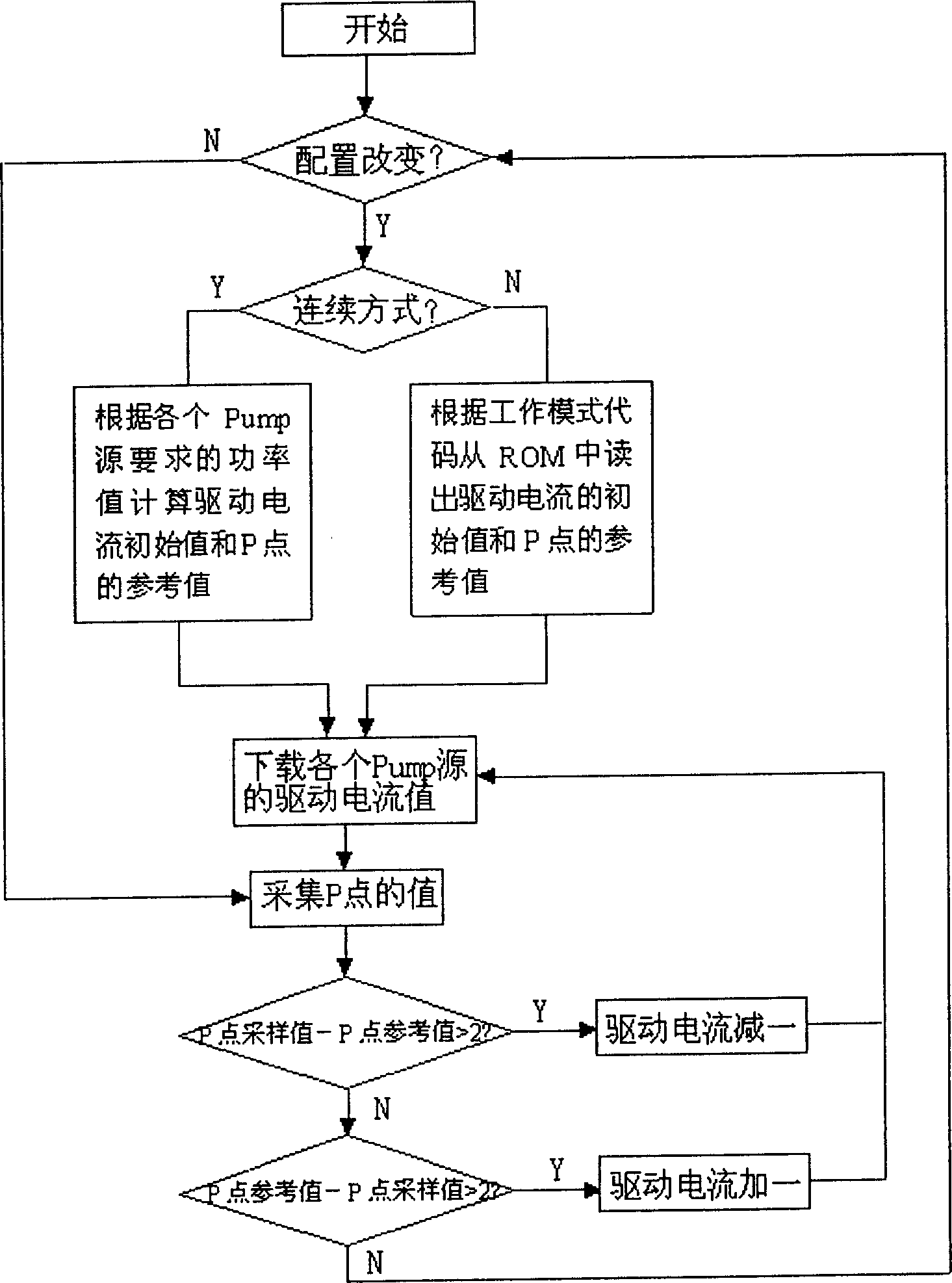

Image

  • Technique of feedback loop for monitoring back light and controlling circuit in Raman amplifying sub system
  • Technique of feedback loop for monitoring back light and controlling circuit in Raman amplifying sub system
  • Technique of feedback loop for monitoring back light and controlling circuit in Raman amplifying sub system

Examples


Embodiment example

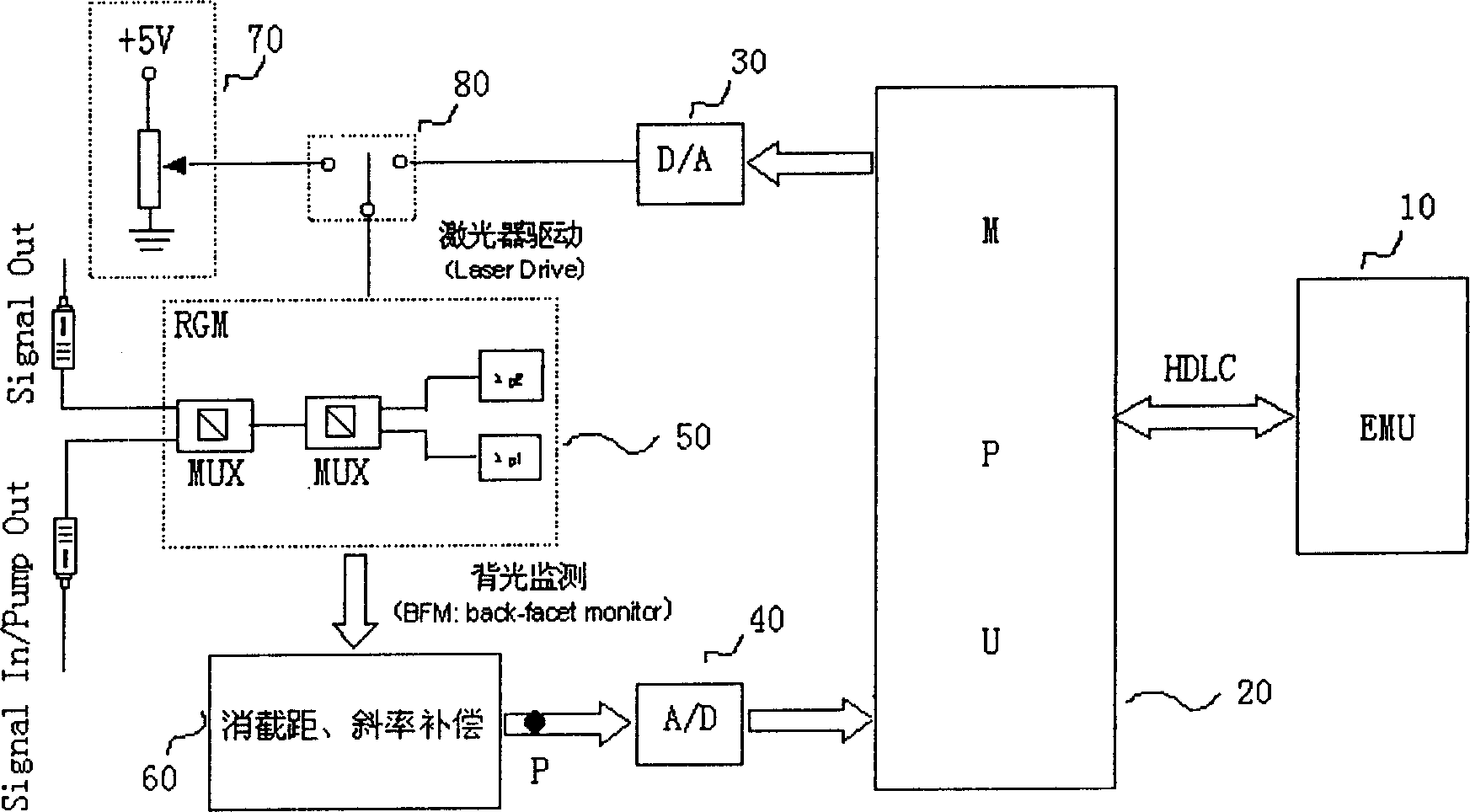
[0018] The backlight monitoring feedback loop technology disclosed in the present invention uses energy detection to detect the backlight output power of the pump laser as a feedback control signal, directly configures and controls the pump output power, and does not need to extract part of the output pump light The energy is detected, and at the same time, the discreteness of the pump laser is solved by using the intercept and slope compensation techniques.

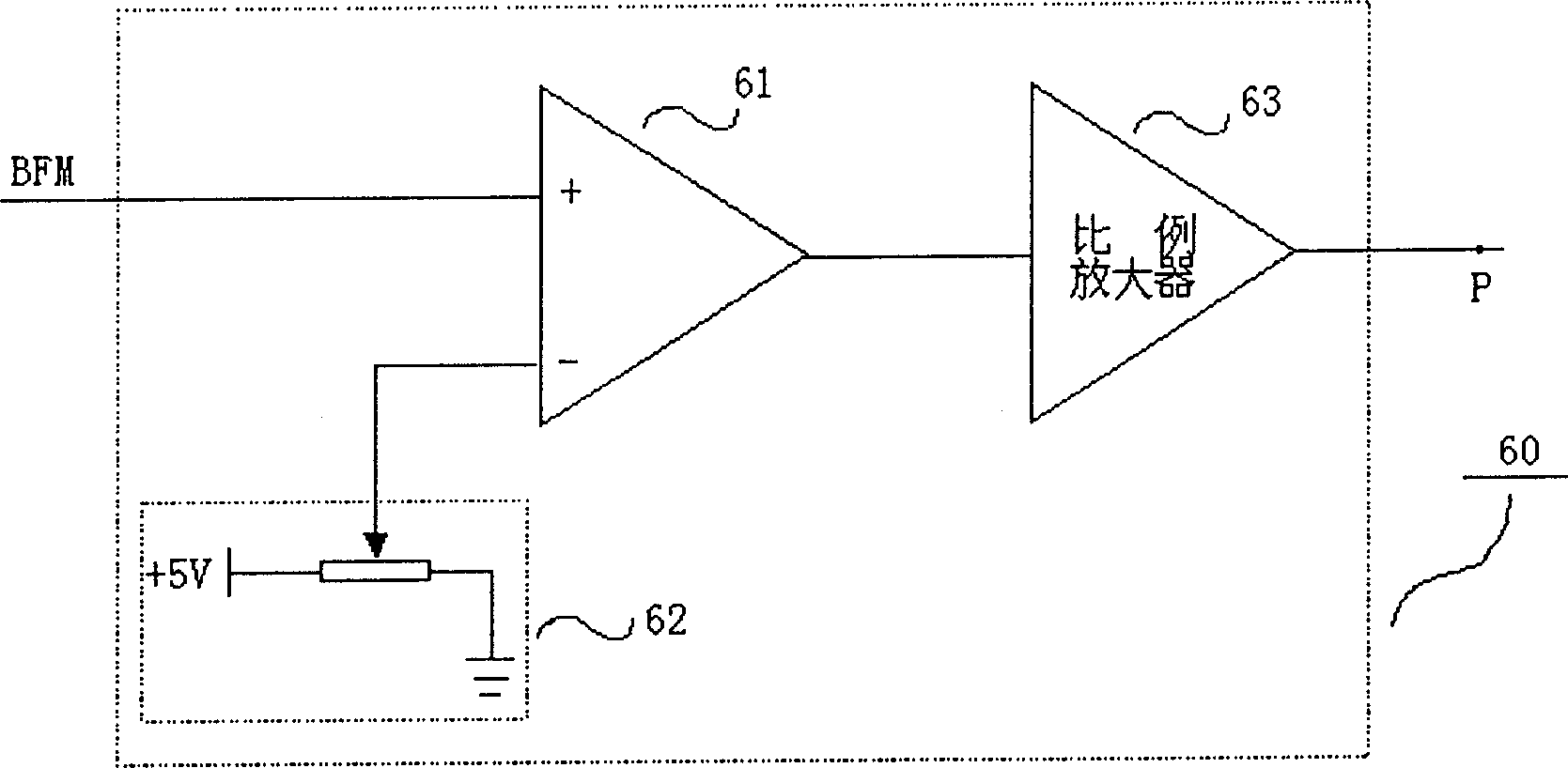
[0019] figure 2 A specific embodiment of the backlight monitoring feedback loop control circuit of the present invention is given, as can be seen from the figure, the backlight monitoring feedback loop (BFM Feedback Loop) is similar to the usual laser automatic power control circuit, but it includes a larger The feedback loop is characterized in that the loop includes a microprocessor (MPU) 20 and an intercept and slope compensation unit 60 .

[0020] In an embodiment of the present invention, the backlight monitoring ...


PUM


Abstract

Output power of Raman pump light is measured indirectly, and parameters of each pump laser are configured and managed. The characters are that measured output power of backlight of pump laser is as feedback control signal. After process of resolving intercept and compensating slope, the sampled value P1 of pump output power is obtained. Output powers of multiple lasers are configured and controlled automatically by using a feedback loop control circuit including microprocessor, which collects P1 as a controlling reference. The controlling and configuring functions are realized through adjusting current for driving pump laser by using microprocessor.

Description

technical field [0001] The invention relates to a backlight monitoring feedback loop technology and its control circuit in a Raman amplification subsystem, which is applied in the field of telecommunication transmission, especially relates to optical fiber communication systems that require optical amplification, such as high-speed, long-distance or ultra-long-distance intensive Wavelength division multiplexing (DWDM) system and high-speed, single-channel optical synchronous digital network (SDH), especially for Raman amplifier subsystems, can also be used for other optical amplifier devices that require flexible configuration of pump laser power. Background technique [0002] Raman amplification is a kind of optical amplification technology, usually used in the field of optical fiber communication. The Raman fiber amplifier has a simple structure, mainly composed of a pump source and an optical fiber. Unlike erbium-doped fiber amplifiers (EDFA), Raman fiber amplifiers have...

Claims


Application Information

Patent Timeline
Patent Type & Authority Applications(China)
IPC IPC(8): G02F1/39H04B10/071
Inventor 刘贤炳谢秋红王红启郭正钧杨铸杨壮
Owner FENGHUO COMM SCI & TECH CO LTD
Learn More