Probe memory device and method for detecting data in probe memory device

A probe storage and probe technology, used in data recording, measurement devices, information storage, etc., to achieve the effect of low power consumption and improved reading speed

Inactive Publication Date: 2004-03-17
IBM CORP
View PDF1 Cites 1 Cited by
  • Summary
  • Abstract
  • Description
  • Claims
  • Application Information

AI Technical Summary

Problems solved by technology

Another problem encountered with time-multiplexed read operations based on thermomechanical detection stems from the inherent limitation of the achievable data rate determined by the cantilever temperature time constant

Method used


Image

  • Probe memory device and method for detecting data in probe memory device
  • Probe memory device and method for detecting data in probe memory device
  • Probe memory device and method for detecting data in probe memory device

Examples


Embodiment Construction

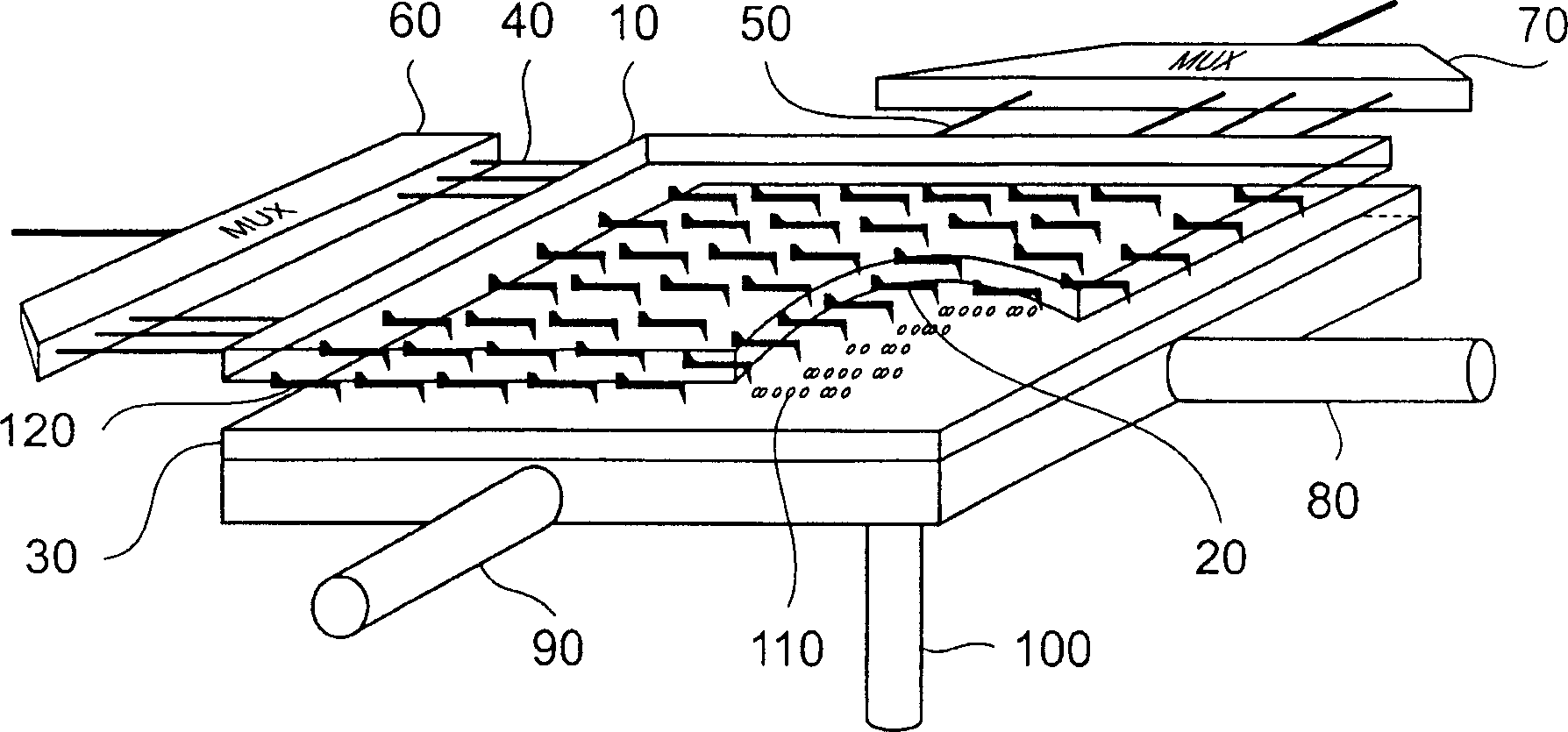
[0027] First refer to figure 1, one example of a probe memory device embodying the present invention includes a substrate 10 having a two-dimensional array 120 of probe cantilever sensors 20 facing a storage surface 30 . The cantilever 20 is connected to a row conductor 40 and a column conductor 50 . Each suspension 20 is addressed by a different combination of row 40 and column 50 conductors. Row conductors 40 are selectively addressed by row multiplexers 60 . Similarly, column conductors 50 are selectively addressed by column multiplexers 70 . The storage surface 30 is mounted on a scanning mechanism consisting of an x-position transducer 80 , a y-position transducer 90 and a z-position transducer 100 . In operation, z-position transducer 100 moves storage surface 30 closer to or away from array 120 . The x-position transducer 80 and the y-position transducer 90 move the storage surface 30 in an orthogonal direction relative to the array 120 and in a plane parallel to th...


PUM

PropertyMeasurementUnit
diameteraaaaaaaaaa

Abstract

A probe-based storage device comprises a storage surface for storing data represented by deformations in the surface. A probe faces the surface and includes a resonant circuit having a reactance dependent on deflection of the probe relative to the surface. A scanner is provided for scanning the probe across the surface such that the probe follows said deformations. A detector reads data stored on the surface by detecting variation of the resonant frequency of said circuit.

Description

technical field [0001] The present invention relates to a method and a device for reading data in a probe data storage device. Background technique [0002] Technologies such as atomic force microscopy (AFM) and scanning tunneling microscopy (STM), which use nanoscale tips (tips) to image and study material structures at the atomic level, have also found applications in ultra-high-density storage devices [1-4]. An example of such a device is found in [5]. In this device, information is stored as a sequence of "pit" and "no pit" written on a polymer storage surface by an array of cantilever, each carrying a tip. The cantilever and its tip are selectively heated to write data onto the surface. Heating each tip sufficiently will cause a corresponding deformation of the adjacent surface of the tip. The stored information is read back by treating each cantilever as a thermomechanical sensor in a circuit that is electrically equivalent to a first order approximation of a curren...

Claims


Application Information

Patent Timeline
Patent Type & Authority Applications(China)
IPC IPC(8): G01Q60/46G01Q80/00G06F12/08G11B9/00G11B9/06G11B9/14G11B11/16G11B11/26
CPCG11B11/16G11B2005/0021G11B9/1409G11B9/14G11B9/1418B82Y10/00G06F12/08
Inventor 乔万尼·彻鲁比尼
Owner IBM CORP
Why Eureka
Try Eureka