Method for monitoring overlaying alignment on wafer

A wafer and overlay error technology, applied in the field of monitoring overlay alignment accuracy, can solve problems such as uncertain relative test accuracy

Inactive Publication Date: 2004-03-17
MACRONIX INT CO LTD
View PDF0 Cites 5 Cited by
  • Summary
  • Abstract
  • Description
  • Claims
  • Application Information

AI Technical Summary

Problems solved by technology

Also, because the machines used to do the testing are themselves used to make the wafers, the relative accuracy of the testing is uncertain

Method used


Image

  • Method for monitoring overlaying alignment on wafer
  • Method for monitoring overlaying alignment on wafer

Examples


Embodiment Construction

[0012] The preferred embodiments of the present invention will be described in detail below with the accompanying drawings. Whenever possible, the same reference numbers will be used when referring to the same or like components in the drawings.

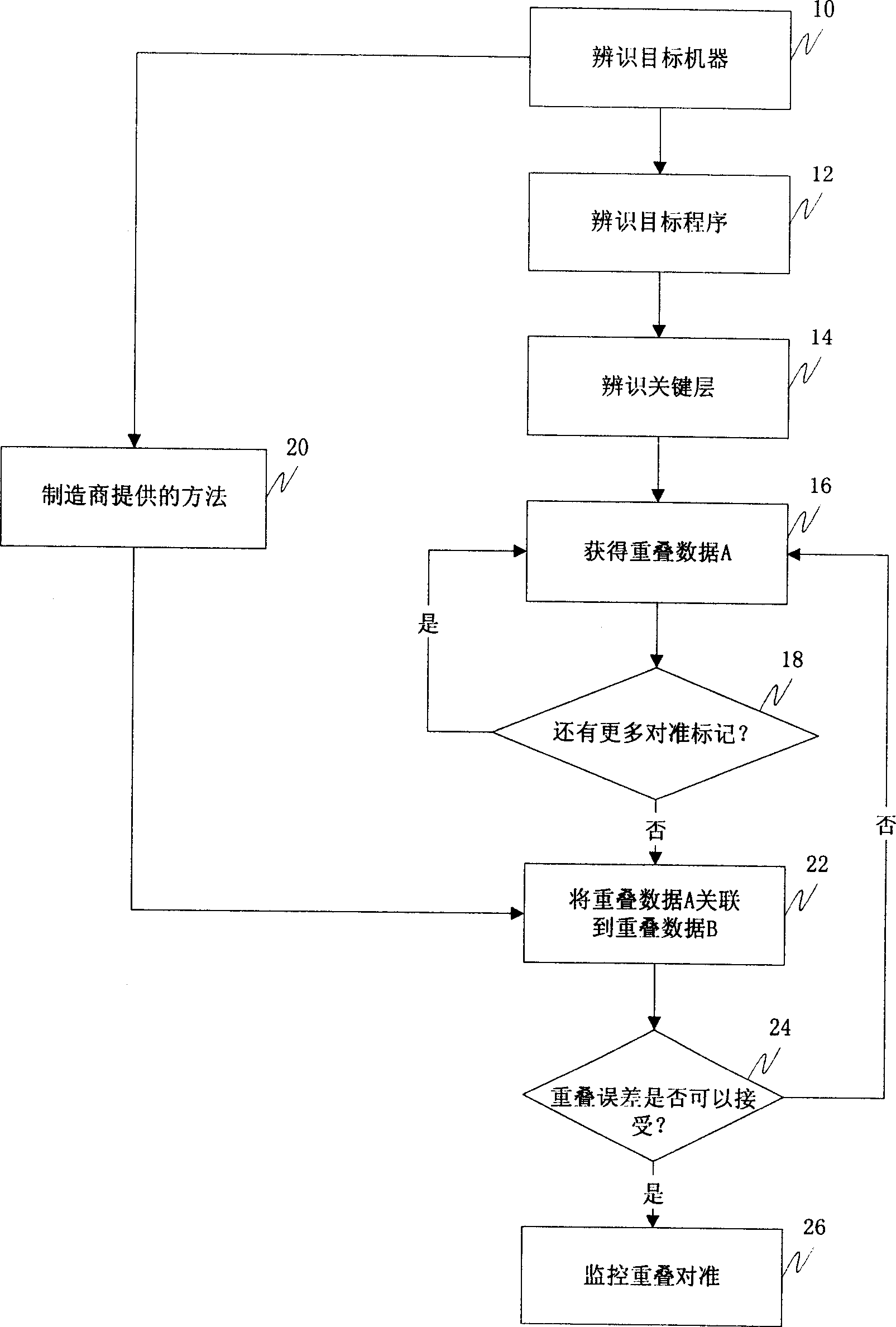
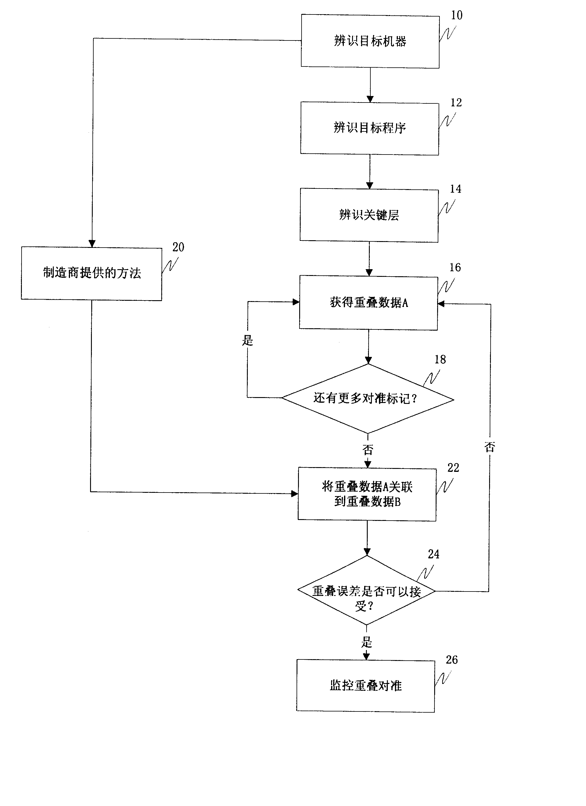
[0013] The present invention provides a monitoring system that improves upon and replaces known methods (such as machine pair testing) and is used to monitor overlay alignment. The monitoring system of the present invention only needs to use five positioning patterns to monitor overlay alignment. Since only a few positioning patterns need to be used to measure overlay data, the down-time of the stepper can be greatly reduced. In addition, the monitoring system of the present invention will also improve the accuracy and reliability of known alignment monitoring methods because the overlay data used to monitor overlay alignment does not need to come from the same stepper.

[0014] figure 1 It is a flowchart of an embodiment of the m...


PUM


Abstract

A method for monitoring overlay alignment on a wafer that includes identifying a target machine, identifying a target process, identifying a plurality of critical layers, obtaining a plurality of overlay data from at least one of designated registration patterns on the wafer as baseline data, providing a plurality of reference overlay data, correlating the plurality of the reference overlay data with the baseline data to obtain overlay error, comparing the overlay error with specifications of the target machine, accepting the baseline data when the overlay error is within the specifications, and performing overlay alignment monitoring with the baseline data.

Description

technical field [0001] The present invention relates to a semiconductor manufacturing process, and more particularly to a method of monitoring the accuracy of overlay alignment during photolithographic steps. Background technique [0002] In the semiconductor manufacturing process, a plurality of integrated circuits can be manufactured on a silicon wafer, and several semiconductor material layers with different patterns and circuit layouts will cover one another at a predetermined position. At various stages in the manufacturing process, a machine called a stepper is used to expose the photoresist with ultraviolet light through a mask or reticle, and to Transfer the circuit layout pattern onto the photoresist layer. The circuit layout pattern is transferred to the photoresist through the grating in a step-and-repeat manner. The grating moves a predetermined distance at a time, exposing the pattern to the photoresist and developing it. The grating is continuously moved to ...

Claims


Application Information

Patent Timeline
Patent Type & Authority Applications(China)
IPC IPC(8): G03F7/20G06F17/50G06F19/00H01L21/027H01L21/66
CPCG03F7/70633
Inventor 彭宗翰简鼎杰刘宗鑫徐志嘉
Owner MACRONIX INT CO LTD
Why Eureka
Try Eureka