Ballast circuit for operating a discharge lamp

A ballast and discharge lamp technology, applied in the field of electronic discharge lamp ballasts, can solve problems such as complex circuit configuration and increased manufacturing costs

Inactive Publication Date: 2004-03-17
MATSUSHITA ELECTRIC WORKS LTD
View PDF1 Cites 7 Cited by
  • Summary
  • Abstract
  • Description
  • Claims
  • Application Information

AI Technical Summary

Problems solved by technology

While the prior art successfully avoids applying high voltages to the detector, the detector must be constructed to derive the width of the change in voltage appearing across the capacitor

Method used


Image

  • Ballast circuit for operating a discharge lamp
  • Ballast circuit for operating a discharge lamp
  • Ballast circuit for operating a discharge lamp

Examples


Embodiment Construction

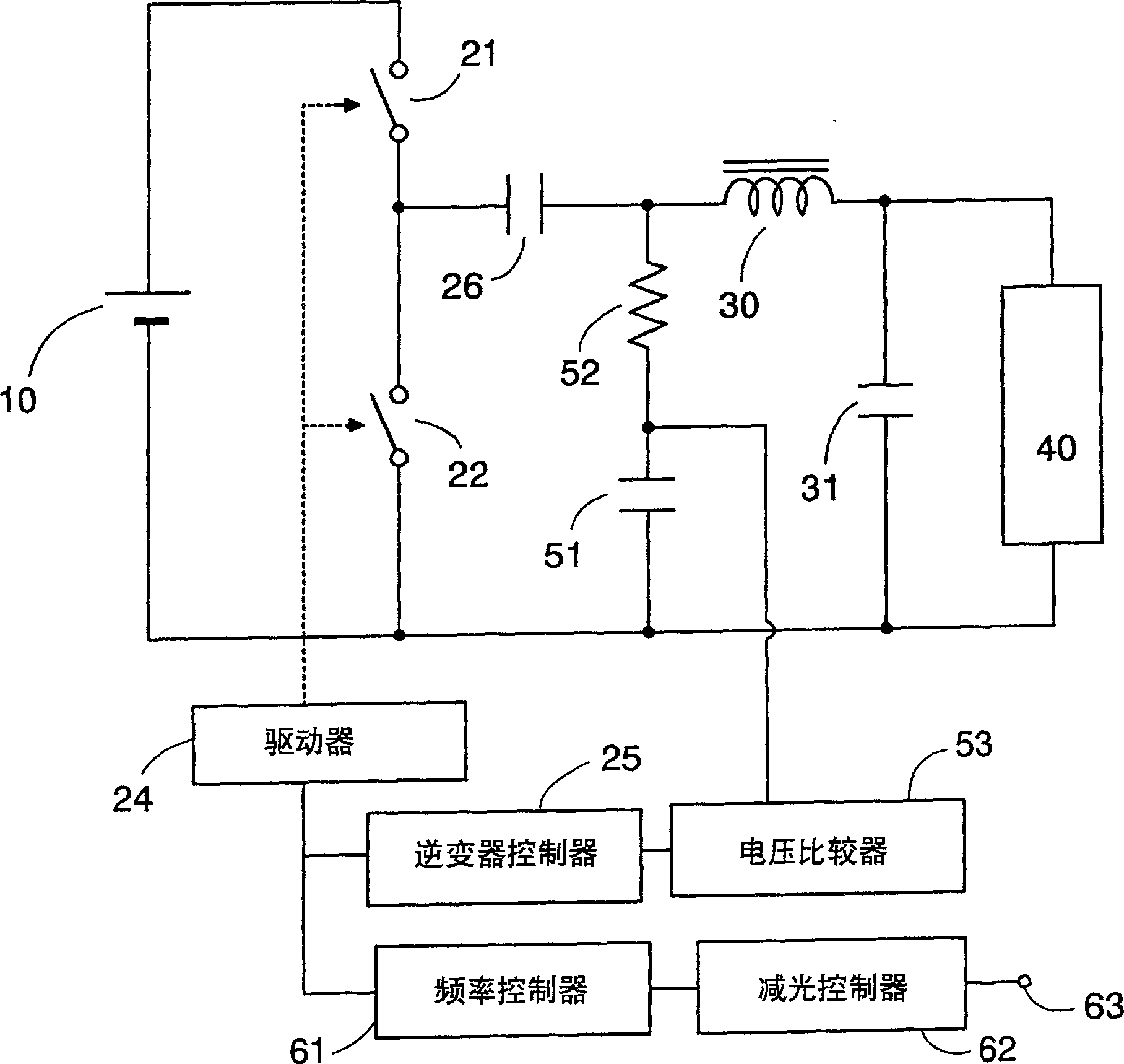
[0014] now refer to figure 1 , shows a ballast circuit for operating a discharge lamp according to a preferred embodiment of the present invention. The ballast circuit includes a DC voltage power supply 10 and a pair of first and second inverter switches 21 and 22, the DC voltage power supply 10 provides a constant DC voltage, and a pair of first and second inverter switches 21 and 22 across It is connected in series on the DC voltage source 10 and driven by a driver 24 to be switched on and off alternately under the control of an inverter controller 25 . The first inverter switch 11 defines a high-side switch, while the second inverter switch 12 defines a low-side switch, one end of which is connected to the ground of the circuit. The circuit also includes a series of resonant circuits composed of an inductor 31 and a capacitor 32, the inductor 31 and the capacitor 32 are connected in series with the blocking capacitor 26 across the second inverter switch 12, and one end of ...


PUM


Abstract

A ballast circuit for a discharge lamp capable of protecting the circuit when the lamp reaches its end of life with a cost effective circuit arrangement. The circuit includes a DC voltage sensing network for sensing a DC voltage which appears as a consequence of the lamp reaching its end of life. Upon the sensed DC voltage exceeding a threshold, a control is made to limit or stop supplying an output power to the lamp for protecting the ballast circuit from an otherwise generating excessive current. The sensing network is composed of a DC sensing capacitor and a resistor which are connected in circuit outside of a resonant circuit responsible for generating a high frequency voltage to operate the lamp. Thus, the DC sensing capacitor can be kept free from the high voltage generated by the resonant circuit and be of less cost for reducing a manufacturing cost.

Description

technical field [0001] The present invention relates to a ballast circuit for operating a discharge lamp. In particular, the invention relates to an electronic discharge lamp ballast having circuit protection for end of lamp life state. Background technique [0002] In order to protect the electronic ballast from overcurrent flowing through the ballast circuit due to the lamp reaching the end of its life state, prior art electronic ballasts are designed to detect the end of lamp life and limit the ballast once end of life is detected. The streamer works. A typical example of an electronic ballast having such protection is disclosed in Japanese Patent Laid-Open No. JP11-31594. The disclosed ballast utilizes a voltage detector to sense the lamp voltage, ie, the voltage across the lamp, for determining whether the lamp voltage exceeds a predetermined threshold indicated by the lamp reaching the end of its life. However, the ballast's detector is required to withstand the high...

Claims


Application Information

Patent Timeline
IPC IPC(8): H05B41/24H05B41/285H05B41/298H05B41/392
CPCH05B41/2855H05B41/2985Y10S315/04
Inventor 西本和弘滨本胜信水川宏光
Owner MATSUSHITA ELECTRIC WORKS LTD
Why Eureka
Try Eureka