Apparatus for supporting burner of drier

A support device and burner technology, applied in the direction of dryer, drying, combustion type, etc., can solve the problems of increasing manufacturing cost, increasing assembly operation process, reducing assembly efficiency, etc., and achieve the effect of reducing the number and improving assembly work

Inactive Publication Date: 2004-04-07
LG ELECTRONICS INC
View PDF0 Cites 6 Cited by
  • Summary
  • Abstract
  • Description
  • Claims
  • Application Information

AI Technical Summary

Problems solved by technology

[0012] In order to fix the supporting part 40 on the base 30, a plurality of fastening screws 42 are required, which leads to an increase in the number of parts, thus increasing the manufacturing cost
In addition, the fastening operation of each fastening screw 42 will result in an increase in assembly operation steps, thereby greatly reducing assembly efficiency.

Method used


Image

  • Apparatus for supporting burner of drier
  • Apparatus for supporting burner of drier
  • Apparatus for supporting burner of drier

Examples


Embodiment Construction

[0032] Preferred embodiments of the present invention will now be described in detail with reference to the embodiments shown in the accompanying drawings.

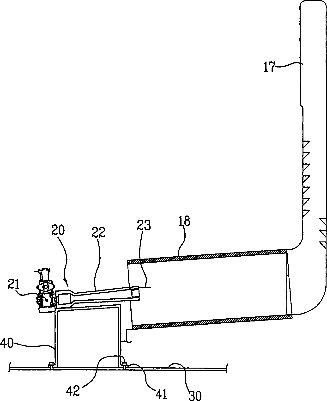
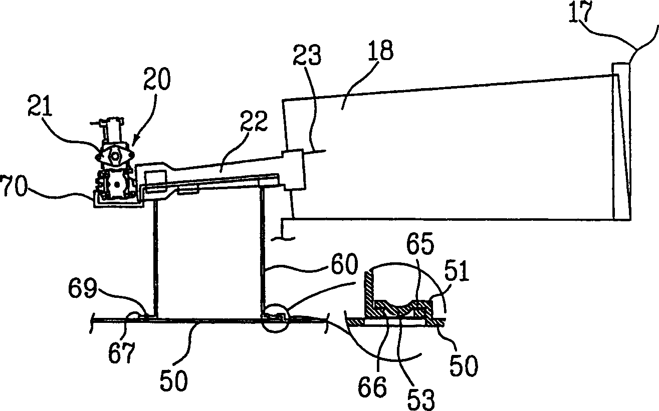
[0033] image 3 is a cross-sectional view of a burner support device for a dryer according to the present invention, Figure 4 shows a perspective view of the burner base and the support of the burner support arrangement according to the invention, and Figure 5 Shown is a plan view of a burner support arrangement according to the invention, wherein the support is mounted on a base.

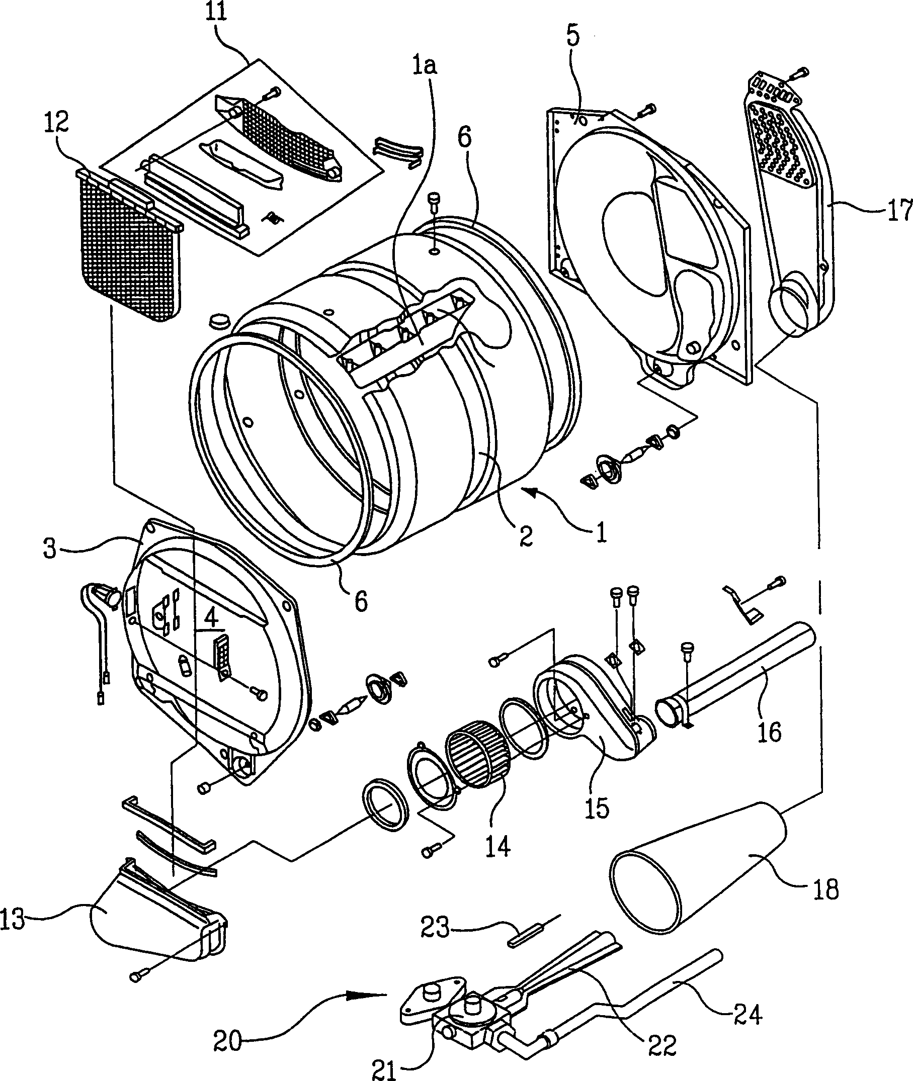
[0034] As previously stated, the burner support hereinafter is figure 1 Part of dryer shown. The burner support device according to the invention can be used in any device having a burner, such as a combination washer / dryer, as well as in a dryer.

[0035] Such as image 3 As shown, the burner 20 is provided on the bottom surface of the box 50 to generate hot air. The burner 20 is a gas burner, and includes a burner body 21 for injecti...


PUM


Abstract

A device for supporting a burner (20) and a dryer having the same are disclosed, in which a structure for supporting the burner is simplified, thereby decreasing the manufacturing price and fabricating of the device is easy. The device for supporting the burner includes a base (70), a burner generating a hot air, a support member (60) having a main connecting part provided between the base and the burner for being detachably inserted to the base so as to support the burner.

Description

technical field [0001] The present invention relates to a dryer, and more particularly to a device for supporting a burner for generating hot air to dry clothes and a dryer having the same. Background technique [0002] Generally, a dryer is a device for drying clothes by means of hot and humid air, and includes a burner that generates hot and humid air, that is, heated air. [0003] figure 1 It is an exploded three-dimensional schematic diagram of a common dryer, figure 2 is a cross-sectional view of a common burner support for a dryer. [0004] Such as figure 1 As shown, the dryer comprises a drum 1 having a casing (not shown) forming its exterior and inside which objects to be dried can be accommodated. The drum 1 is a cylinder with both ends open, and is driven to rotate by a separate driving unit (not shown). For this purpose, the drum 1 has on its outer surface a belt groove 2 around which a drive belt (not shown) is wound. Moreover, a baffle 1a for flipping the...

Claims


Application Information

Patent Timeline
Patent Type & Authority Applications(China)
IPC IPC(8): F23C5/02D06F58/02D06F58/26F26B21/00
CPCD06F58/263F26B21/00
Inventor 朴秀原金庆秀
Owner LG ELECTRONICS INC
Why Eureka
Try Eureka