Method for transforming energy and vortex tube for carrying out said method

A vortex tube, a technology for converting energy, used in the field of electric power industry

Inactive Publication Date: 2004-04-21
SINTOS SYST OU
View PDF0 Cites 6 Cited by
  • Summary
  • Abstract
  • Description
  • Claims
  • Application Information

AI Technical Summary

Problems solved by technology

In the known application of the Ranke vortex tube, the kinetic energy of the loaded particles, ie the energy generated as a result of the above reaction, has not been used

Method used


Image

  • Method for transforming energy and vortex tube for carrying out said method
  • Method for transforming energy and vortex tube for carrying out said method
  • Method for transforming energy and vortex tube for carrying out said method

Examples


Embodiment Construction

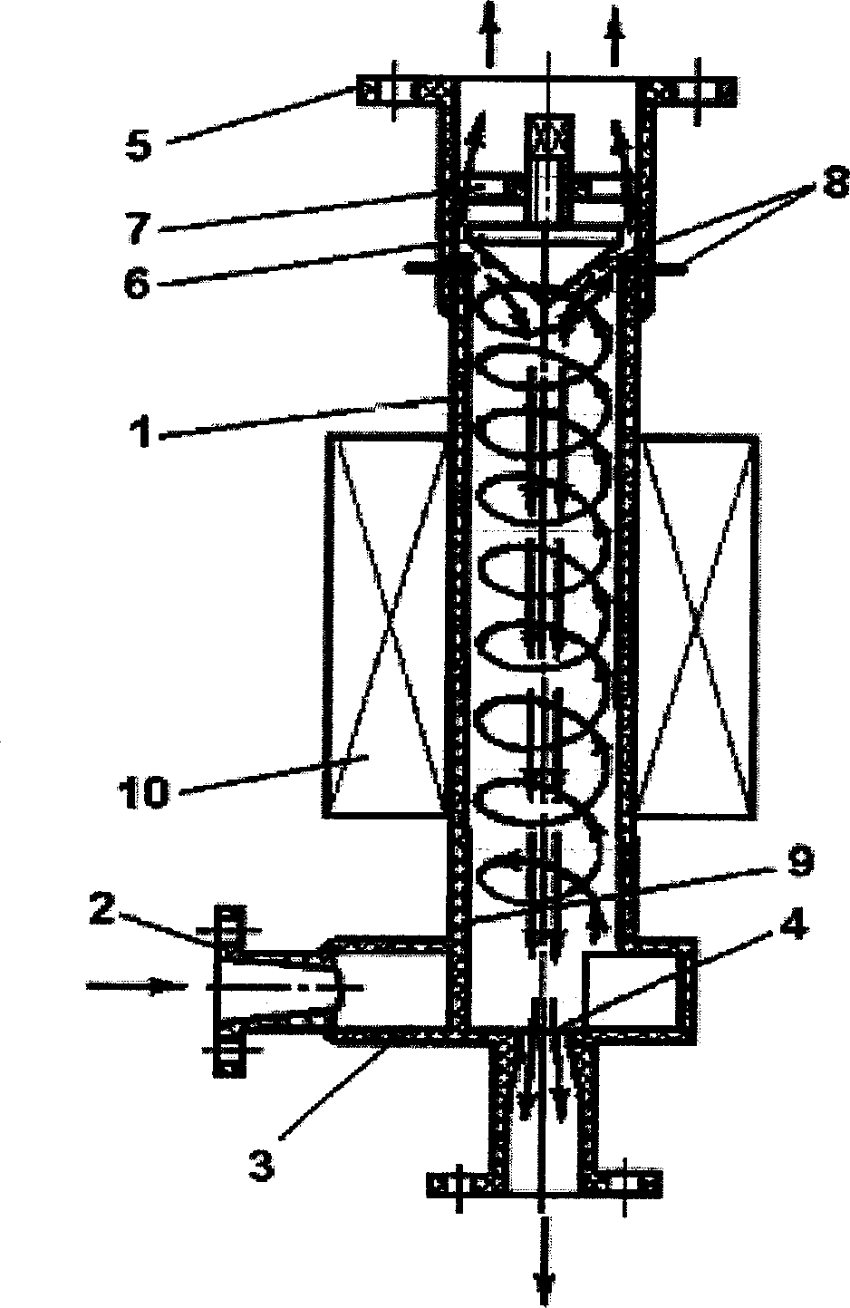
[0028] The present invention will be described with reference to an embodiment of a thermoelectric water generator according to the Gritskevich vortex tube.

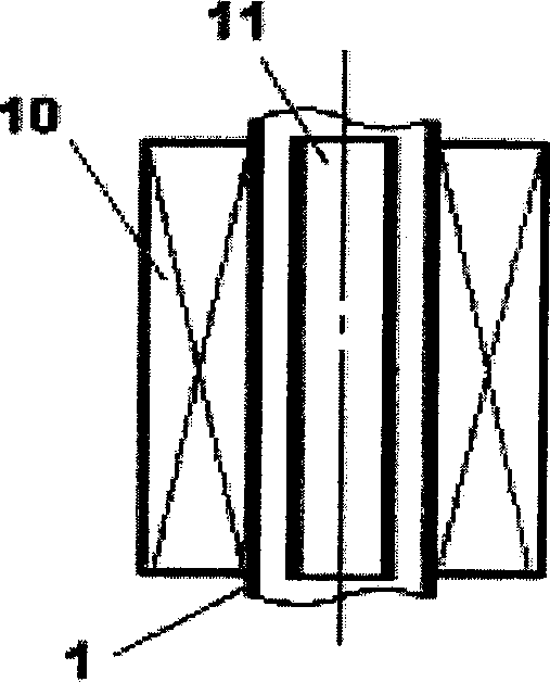
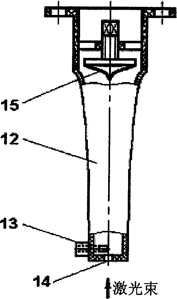
[0029] Such as figure 1 As shown, the vertically placed cylindrical thermoelectric generator includes a tube shell 1 with a cold part, which is converted to a volute swirler 2 through an injection port 3 and a partition plate with an opening 4. The thermal component includes an outlet nozzle 5, an adjustment cone 6 with a shaft adjustment device 7, and a pair of electrodes 8 extending horizontally along the circumference of the gap between the tube shell 1 and the adjustment cone 6. The inside of the tube case 1 is coated with a thin layer of barium titanate (TiBa), and the outside has an electromagnetic winding 10. The tube shell 1, the spiral swirler 2, the adjusting cone 6 and the nozzles 3 and 5 are made of plastic and separated from the ground.

[0030] The cold water flow entering the cold part through the nozzle 3 is...


PUM


Abstract

The invention relates to the electric-power industry and can be used for producing both thermal and electric energy and for measuring the liquid or gas flow temperature. The aim of the invention is to increase the performance of the vortex tube based on Ranke's effect and to extend the functional capabilities thereof for producing electric energy. The inventive methods for transforming energy of a running liquid or gas flow inside the vortex tube using Ranke's effect are carried out by an additional heating of liquid or gas in the hot part of the vortex tube and / or additional production of electric energy taken from windings (10) mounted on the vortex tube-case (1), the said case being made of a dielectric material. The inventive vortex tube for carrying out the said method comprises a tube-case (1) provided with a cyclone (3) at the end side thereof. Though, the said case is not grounded and is made of an electrically non-conductive material with electro-static properties.

Description

Technical field [0001] The present invention relates to the electric power industry, and can be used to produce heat and electric energy and to change the temperature of liquid flow or air flow. Background technique [0002] The method used by French engineer J. Ranke to convert and extract energy using vortex tubes is well known. Initially, vortex tubes were used to separate the airflow into hot and cold jets. The classic Ranke vortex tube [1; 2, p. 108] contains a cylindrical tube with a cyclone at one end and a barrier device, which is connected to one end of the tube shell and at the other end. The side (cold part) has a partition, and the blocking device is an adjustment cone located in a cone opposite to the side of the cyclone (hot part). The compressed gas is sent tangentially into the tube through the cyclone, and is divided into a low temperature (central) part and a high temperature (peripheral) part in the vortex. The low temperature air flow leaves the tube through t...

Claims


Application Information

Patent Timeline
IPC IPC(8): F24J3/00F25B9/04H02N3/00H02K44/08
CPCF05B2260/209F24J3/003F25B9/04H02K44/085F24V40/00H02K44/08
Inventor 奥列格·维亚切斯拉沃维奇·格里茨科维奇鲍里斯·奥列格维奇·格里茨科维奇维克托·瓦西里耶维奇·伊里因斯坦尼斯拉夫·阿法那西耶维奇·里森亚克
Owner SINTOS SYST OU
Why Eureka
Try Eureka