Display mode of medical ambi-plasma power source

A plasma and power source technology, applied in medical science, indicating components, instrument parts, etc., can solve the problems of inconvenient operation for doctors, failure to display dynamic power, display load impedance, etc.

Inactive Publication Date: 2004-04-28
广东合好医疗科技有限公司
View PDF0 Cites 7 Cited by
  • Summary
  • Abstract
  • Description
  • Claims
  • Application Information

AI Technical Summary

Problems solved by technology

The displayed power is the set power, and the dynamic power cannot be displayed
This display mode cannot display the load impedance while displaying the set power, which is very inconvenient for doctors to operate.

Method used


Image

  • Display mode of medical ambi-plasma power source
  • Display mode of medical ambi-plasma power source
  • Display mode of medical ambi-plasma power source

Examples


Embodiment Construction

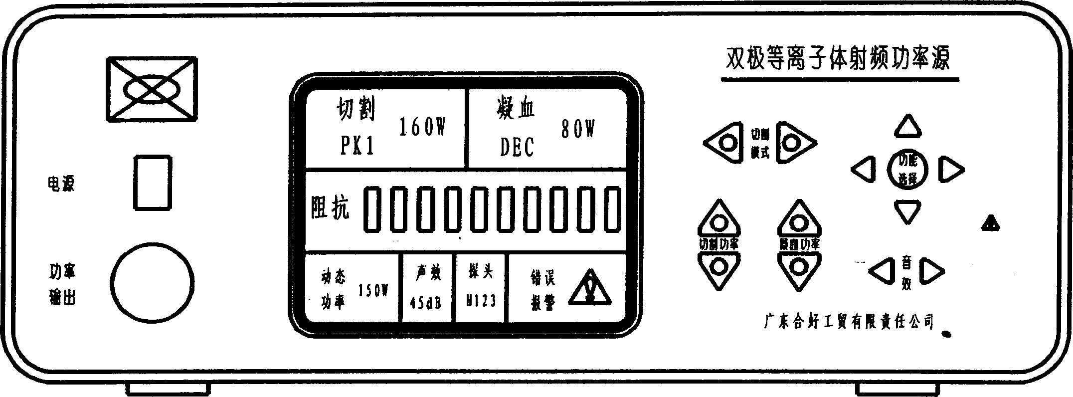
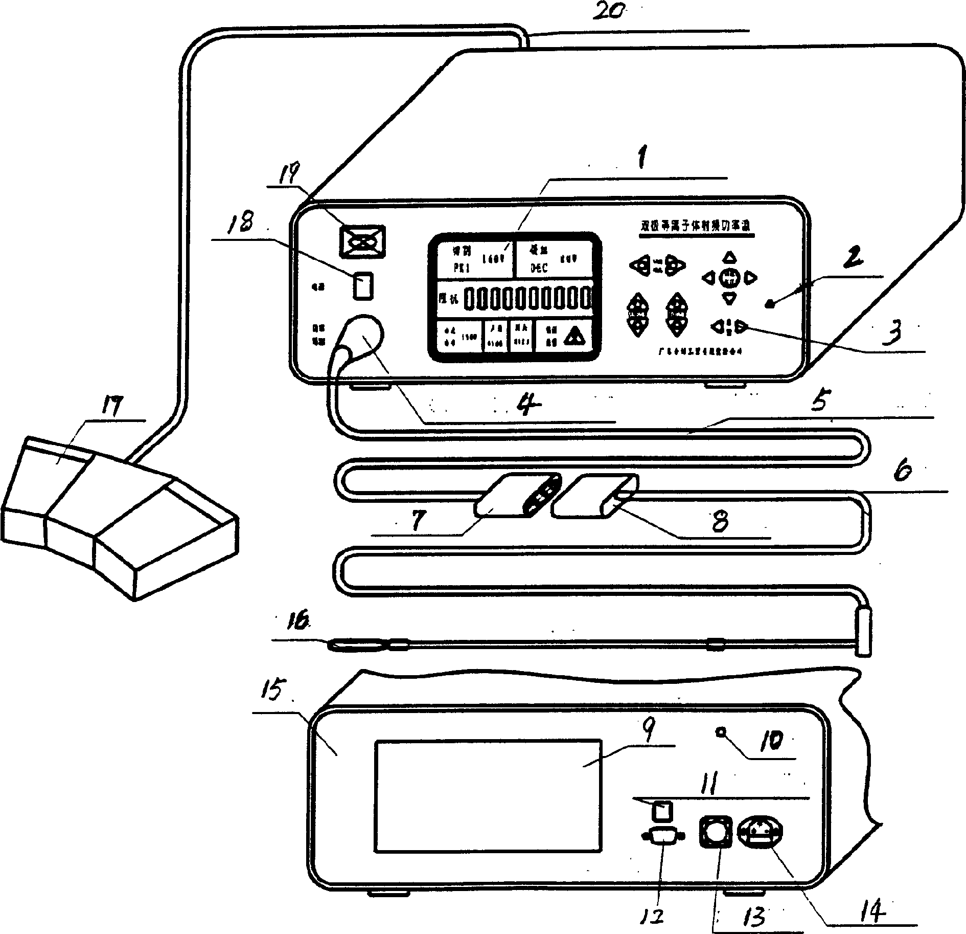
[0016] The middle part of the front panel of the power source is a liquid crystal display, which displays the static and dynamic working parameters of the power source. The upper left middle part is the power switch, which glows green when powered on. The lower left part is the main output connector of the power source. The right side is the keyboard alarm indication.

[0017] The left side of the rear panel of the power source is a cooling plate. The lower right part is arranged with 10 / 100M Ethernet RJ-45 connector, RS-232 connector, foot switch interface, and power input interface.

[0018] The application connection method is: the foot switch is connected to the foot switch interface on the rear panel of the main power source; the cutting head is connected to the main output connector of the power source through an adapter cable.

[0019] When the instrument is working, it will perform a self-test after starting up. After the self-test is passed, it will enter the worki...


PUM


Abstract

The present invention relates to display mode of medical ambiplasma power source, and features the dot matrix display of several parameters, including cutting mode and power, blood coagulation mode and power, dynamic impedance, dynamic output power of the power source, acoustic loudness, probe type and model, error alarm information, etc. The present invention facilitates the electric surgical operation.

Description

Technical field [0001] The invention relates to a display mode, in particular to a display mode of a medical bipolar plasma power source. Background technique [0002] The bipolar plasma cutting device is a surgical device used for electrosurgical treatment of patients, such as the treatment of diseases such as benign prostatic hyperplasia. Two modes of tissue action are produced by adjusting the power of the high-frequency power source. The first mode will generate an ionized plasma halo in the active area of ​​the tissue treatment electrode, and the tissue that enters the high-energy plasma halo is instantly vaporized, and then rinsed with rinsing fluid. rinse off. In the second mode, tissue temperature can be raised rapidly, predictably, and in a controlled manner to melt tissue or seal blood vessels. [0003] In the actual operation process, since the cutting head touches different tissues of the human body, its load impedance can vary from 50Ω to 1000Ω. The power sou...

Claims


Application Information

Patent Timeline
Patent Type & Authority Applications(China)
IPC IPC(8): A61B18/00A61B18/12G12B11/00
Inventor 林敏孙国良王沐刘忠礼
Owner 广东合好医疗科技有限公司
Why Eureka
Try Eureka