
Four-stroke engine

A four-stroke engine and combustion chamber technology, applied in the direction of engine ignition, engine components, combustion engines, etc., can solve the problems that it is difficult to achieve lean combustion and increase fuel costs, and achieve the effect of reducing fuel costs and lean combustion

Inactive Publication Date: 2004-05-05
HONDA MOTOR CO LTD
View PDF1 Cites 0 Cited by
  • Summary
  • Abstract
  • Description
  • Claims
  • Application Information

AI Technical Summary

Problems solved by technology

[0005] In the above-mentioned four-stroke engine of the prior art, since the intake air flowing into the combustion chamber from at least one of the plurality of air inlets collides with the spark plug and disperses in the combustion chamber, the mixed gas in the combustion chamber is stirred, and it is difficult to achieve lean combustion. Possibility of large fuel bills

Method used


Image

  • Four-stroke engine
  • Four-stroke engine
  • Four-stroke engine

Examples


Embodiment Construction

[0022] The implementation of the present invention will be described below according to an embodiment of the present invention shown in the accompanying drawings.

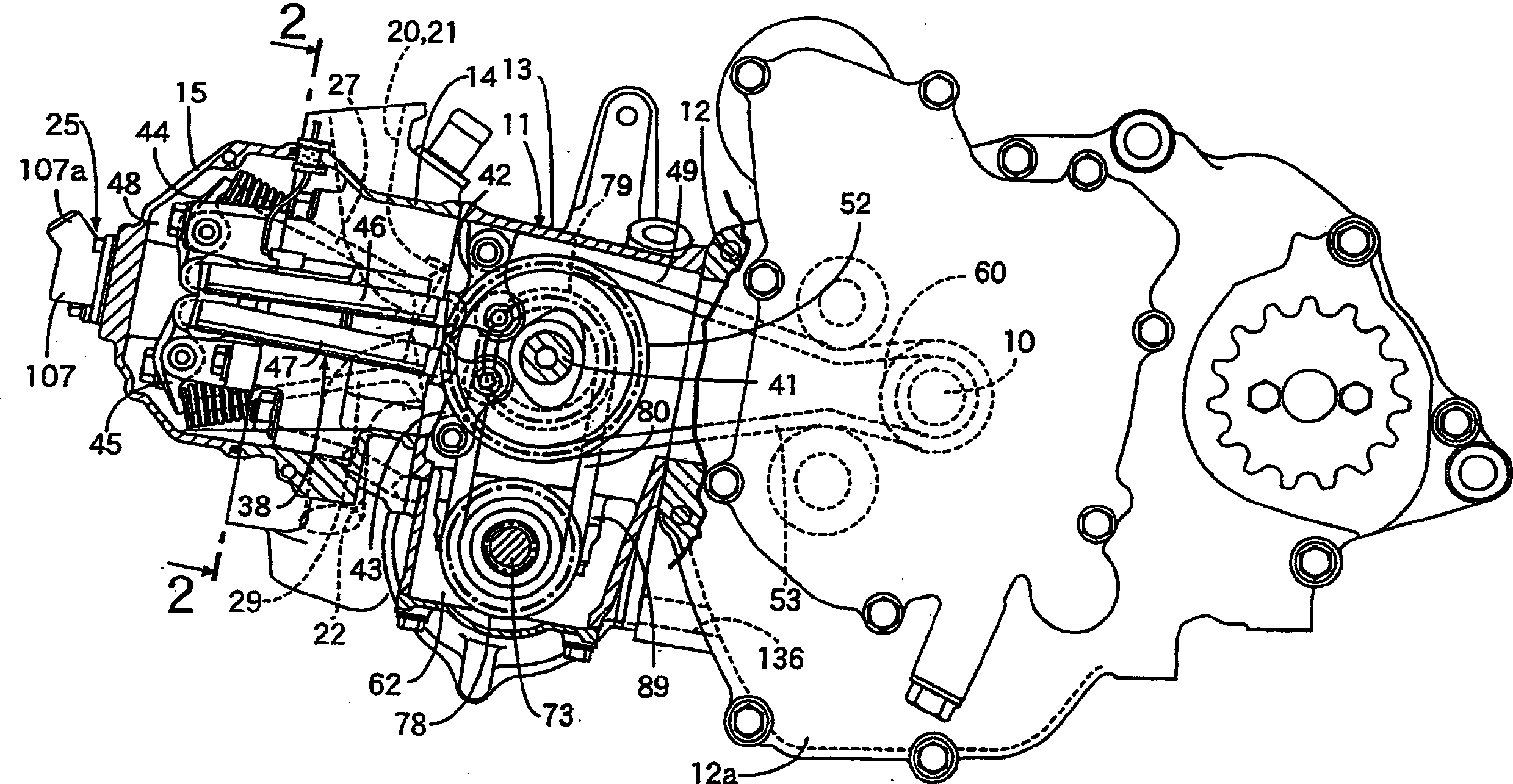
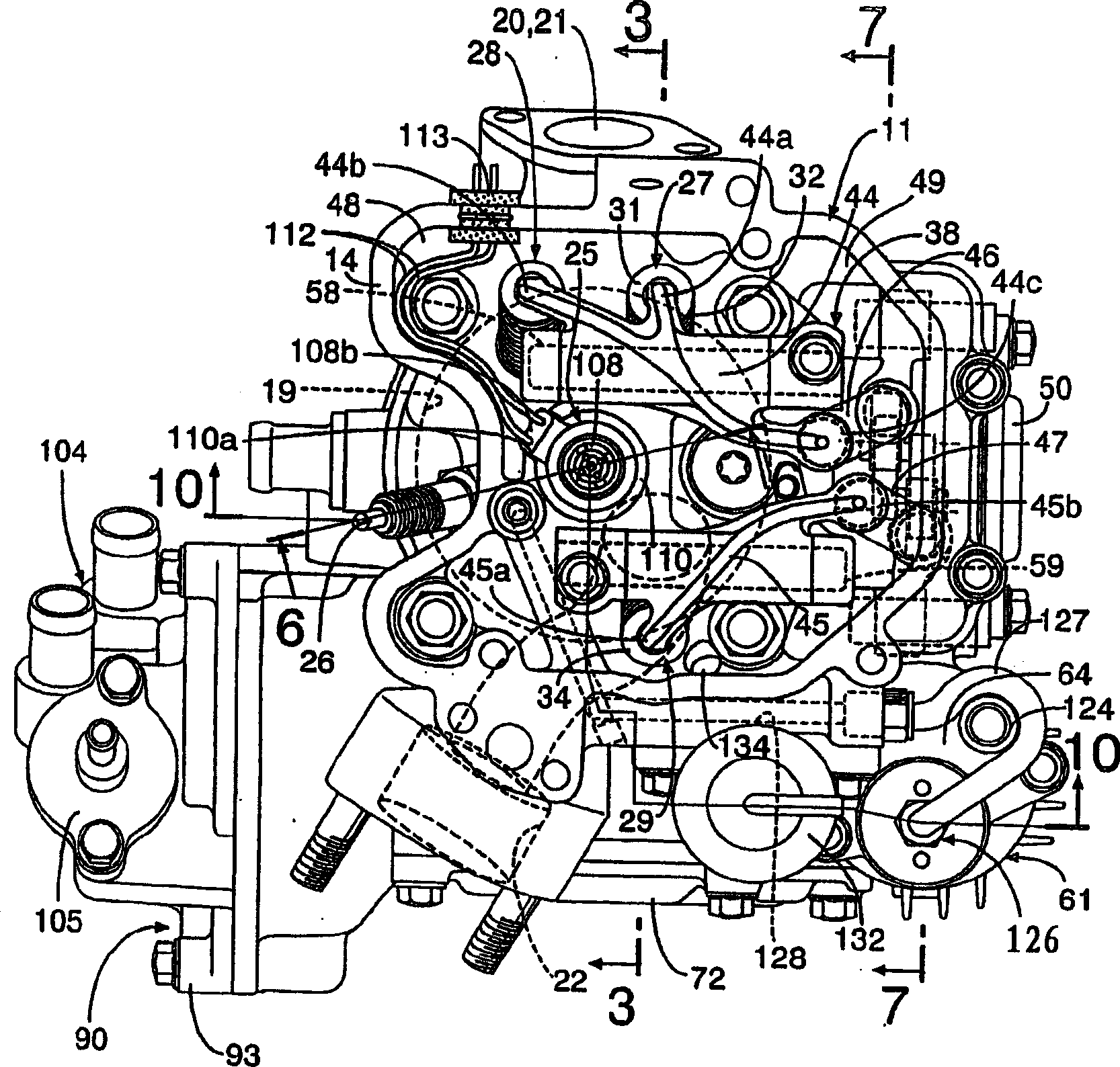
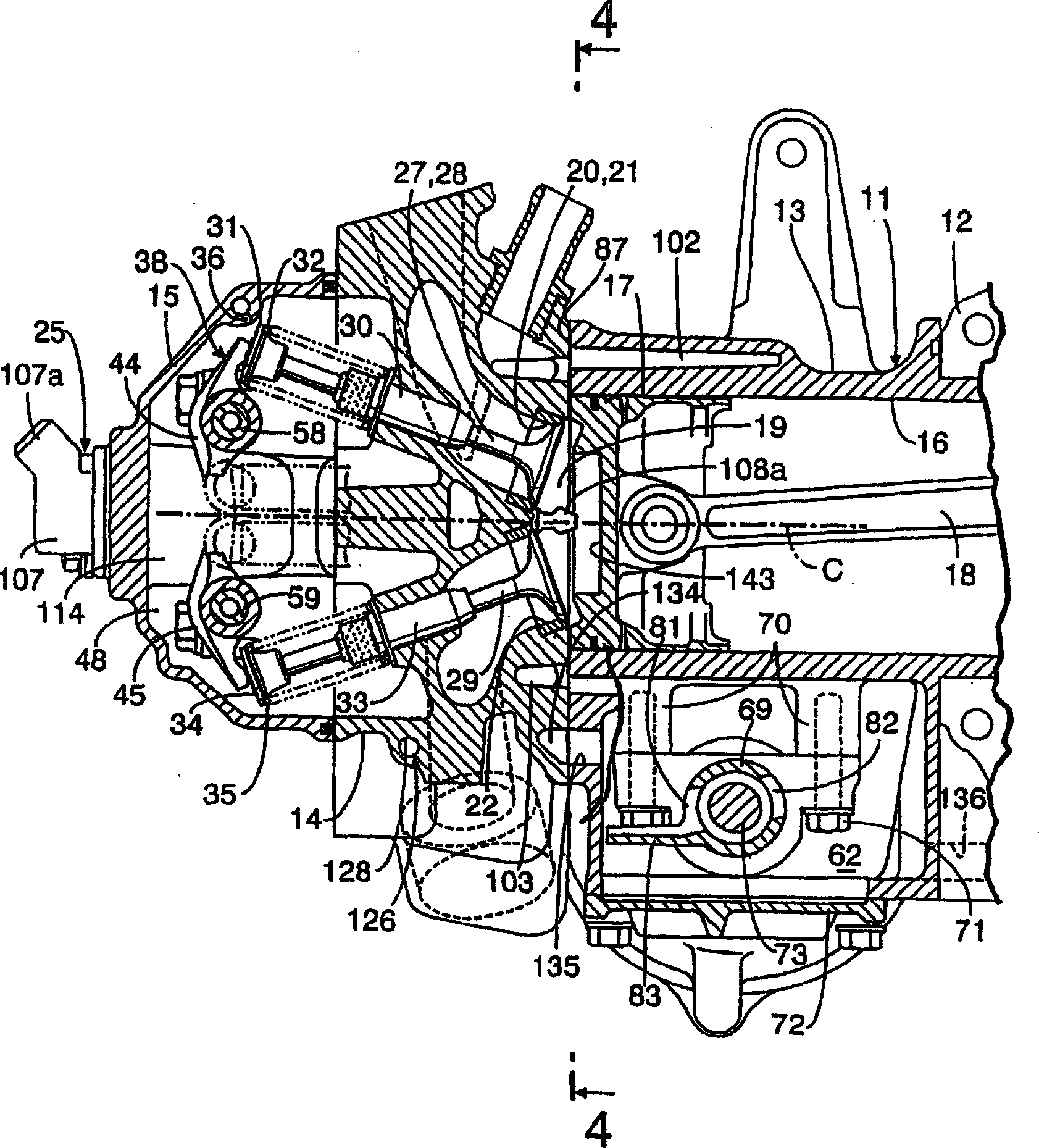
[0023] Figure 1 to Figure 10 is to represent an embodiment of the present invention, figure 1 is a partial longitudinal sectional side view of the engine, figure 2 with the cylinder head removed figure 1 The direction view of the 2-2 line in the middle, image 3 Yes figure 2 3-3 line sectional view, Figure 4 is image 3 4-4 line sectional view, Figure 5 It is the sectional view of line 5-5 in Figure 4, Image 6 is along figure 2 The enlarged cross-sectional view of the cylinder head on line 6-6, Figure 7 Yes figure 2 Sectional diagram of line 7-7, Figure 8 Yes Figure 7 8-8 line sectional view, Figure 9 is Figure 7 Sectional diagram of line 9-9, Figure 10 is along figure 2 Longitudinal side view of the engine on line 10-10.

[0024] First, in figure 1 Among them, the engine main body 11 o...


PUM


Abstract

An ignition plug 26 is attached on a cylinder head 14 at a position shifted from a center of the combustion chamber 19 and corresponding to an air inlet port 20 of a parallel direction one end side of a plurality of the air inlet ports 20, 21 arranged in parallel, and a guide wall 142 guiding intake air flowing in the combustion chamber 19 from the inlet air port 20 on the one end side to bypass the ignition plug 26 is provided on a ceiling wall 19a of the combustion chamber 19 around an opening end of the inlet air port 20 of the one end side to the combustion chamber 19.

Description

technical field [0001] The present invention relates to a four-stroke engine in which a spark plug facing the combustion chamber is mounted on a cylinder head provided with a plurality of intake ports opening to the combustion chamber. Background technique [0002] Conventionally, such a four-stroke engine is known, for example, from Patent Document 1 and the like. [0003] (Patent Document 1) [0004] Japanese Patent Publication No. 5-71767. [0005] In the above-mentioned four-stroke engine of the prior art, since the intake air flowing into the combustion chamber from at least one of the plurality of air inlets collides with the spark plug and disperses in the combustion chamber, the mixed gas in the combustion chamber is stirred, and it is difficult to achieve lean combustion. Possibility of big fuel bill. Contents of the invention [0006] The present invention is proposed in view of this situation, and the purpose is to provide a four-stroke engine capable of perf...

Claims


Application Information

Patent Timeline
Patent Type & Authority Applications(China)
IPC IPC(8): F01L1/00F02B17/00F02B23/10F02B75/12F02F1/24F02M61/14F02P13/00
CPCY02T10/125F02B2075/125Y02T10/123F02B23/101F02B17/005Y02T10/12
Inventor 塙薰上田浩矢栗原博
Owner HONDA MOTOR CO LTD
Learn More