Device and method for separating and recovering cutting fluid and iron filings

A technology for separation and recovery of cutting fluid, applied in separation methods, precipitation separation, chemical instruments and methods, etc., can solve the problems of low recovery efficiency, polluted cutting fluid, and large cutting impact, achieve high utilization rate, reduce work intensity, The effect of increasing usage

Active Publication Date: 2022-07-01
大连博斯特科技有限公司
View PDF17 Cites 0 Cited by
  • Summary
  • Abstract
  • Description
  • Claims
  • Application Information

AI Technical Summary

Problems solved by technology

The cutting fluid in the chip material belongs to industrial sewage. The water-based cutting fluid contains a large amount of sediment after cutting. If the cutting fluid is discharged outside through the drainage system, it will pollute the environment and cause waste of cutting fluid.
At present, the cutting fluid is often recovered by one-tank sedimentation collection method, but the liquid agitation caused by the one-tank sedimentation when injecting cutting fluid brings up the precipitated impurities again, polluting the upper layer of cutting fluid, resulting in the efficiency of cutting fluid separation and recovery. Low, and the quality is not high, and it will have a great impact on cutting when it is used again

Method used


Image

  • Device and method for separating and recovering cutting fluid and iron filings
  • Device and method for separating and recovering cutting fluid and iron filings
  • Device and method for separating and recovering cutting fluid and iron filings

Examples


Embodiment 1

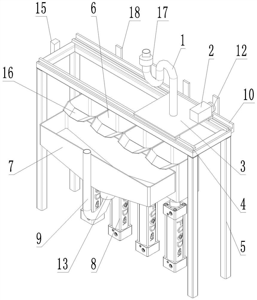
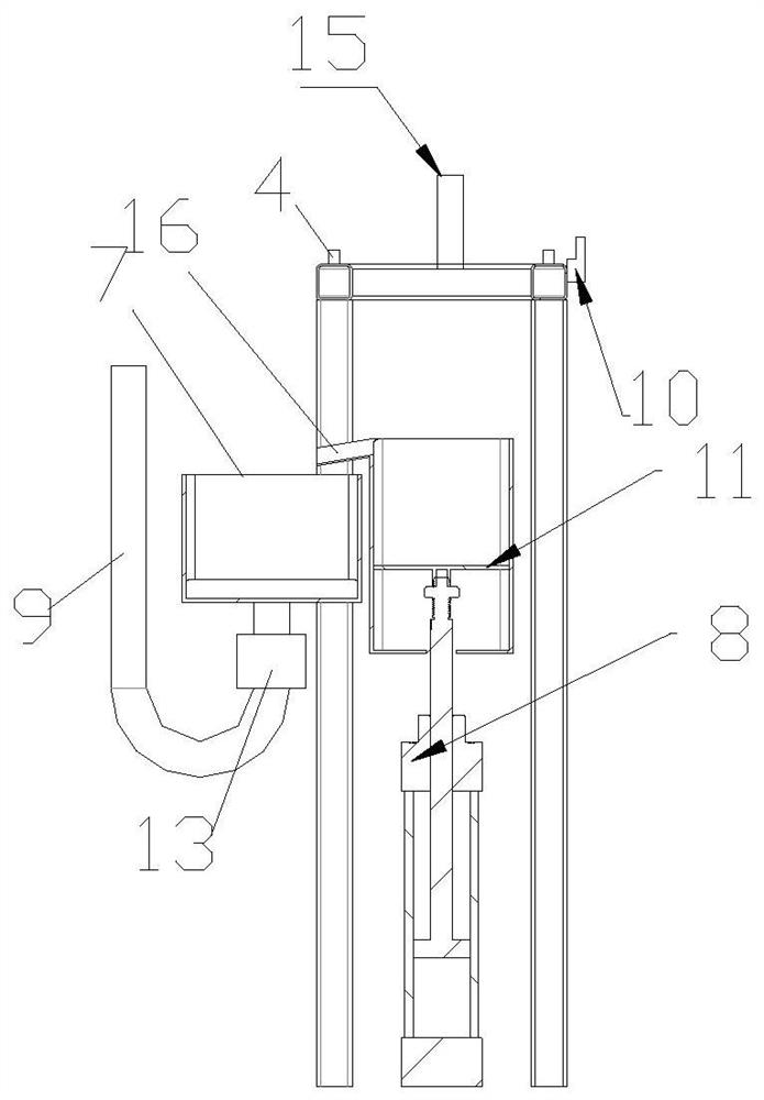
[0032] like Figure 1-3 As shown in the figure, a cutting fluid and iron filings separation and recovery device proposed in this embodiment includes a frame body 5, the top of the frame body 5 is provided with a slide rail 4, and the slide rail 4 is matched with a collection tube that moves along the slide rail 4. 1. A solenoid valve 17 is provided on the collecting pipe 1, and the collecting pipe 1 is connected with a driving mechanism for driving the moving of the collecting pipe 1; On the sliding plate 3, and the bottom end of the collecting pipe 1 penetrates the sliding plate 3; the sliding plate 3 is connected with the motor 2, the drive shaft of the motor 2 is connected with a gear 12, the gear 12 is meshed with a rack 10, and the rack 10 is fixedly connected to the frame At the top of the body 5, when in use, the motor 2 rotates to drive the gear 12 to rotate, and the rotation of the gear 12 will move along the rack 10, thereby driving the collection tube 1 to move left...

Embodiment 2

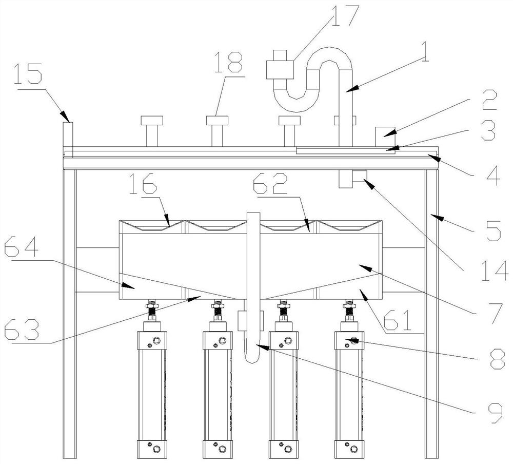
[0058] like Figure 4-5 As shown in the figure, other structures are the same as the first embodiment, the difference is that in this embodiment, the sedimentation tank 6 is not fixedly connected with the frame body 5, and the collection groove 7 can be directly connected with the frame body 5, or can be connected to the frame body 5 through a column or the like The structure is supported on the ground to realize the fixation of the collection tank 7, which is a conventional setting and will not be described again; a plurality of sedimentation tanks 6 arranged at intervals are arranged side by side below the bottom port of the collection pipe 1, and the outer wall of the sedimentation tank 6 is provided with The sliding column 21 is provided with an arc-shaped guide rail 19 on both sides of each sedimentation tank 6. The arc-shaped guide rail can be fixed on the ground or on the frame body. In the groove 20; the sedimentation groove 6 can slide along the arc guide 19.

[0059...


PUM


Abstract

The invention discloses a cutting fluid and iron filings separation and recovery device and method, comprising a frame body, a sliding rail is arranged on the top of the frame body, a collecting pipe is matched with the sliding rail, and the collecting pipe is connected with a driving mechanism; A plurality of sedimentation tanks are arranged at intervals; a collection tank and a material box are arranged on both sides of the sedimentation tank; the sedimentation tank is provided with an arc-shaped guide rail; an ultrasonic level gauge is arranged on the outer wall of the bottom of the collection pipe; A detection mechanism used to detect and identify the position of the collection pipe; one end of the frame body is also provided with a stop switch. After the collection pipe touches the stop switch, it will automatically return to the initial position; each sedimentation tank is equipped with a piston plate. , a hydraulic cylinder is connected at the bottom of the piston plate; a cylinder is hinged on the outer wall of the hydraulic cylinder. The entire device also includes a controller. The invention is provided with a plurality of precipitation tanks, so that the cutting fluid can more fully precipitate impurities, and the separation of the cutting fluid and the iron filings can be automatically realized, and the separation effect is good, saving time and effort.

Description

technical field [0001] The invention relates to the technical field of cutting fluid collection, in particular to a device and method for separating and recovering cutting fluid and iron filings. Background technique [0002] In CNC machine tool processing, whether it is a lathe or a machining center and other processing machinery, it is necessary to clean up the chips in time. At present, the chain plate type chip conveyor is widely used to clean the chips. The chip conveying groove conveys the chips formed by the CNC machine tool to the scraper of the chip conveyor, and the scraper pushes and scrapes the chip through the opening at the bottom of the groove at the end of the chip conveyor to the discharge box for further processing. [0003] A large amount of cutting fluid is used in the machining process of CNC machine tools to protect the tool and improve the cutting efficiency. A large amount of cutting fluid is also mixed in the discharged chips. The cutting fluid that...

Claims


Application Information

Patent Timeline
Patent Type & Authority Patents(China)
IPC IPC(8): B23Q11/10B01D21/00B01D21/02B01D21/24B01D21/34
CPCB23Q11/10B01D21/00B01D21/02B01D21/2444B01D21/245B01D21/34
Inventor 李贤明李亚鹏李红佳
Owner 大连博斯特科技有限公司
Why Eureka
Try Eureka