Ice machine

An ice maker and rack technology, which is applied in the field of ice maker, can solve the problems of energy consumption, slow generation of ice cubes, waste, etc.

Inactive Publication Date: 2004-05-05
SAMSUNG GWANGJU ELECTRONICS CO LTD
View PDF1 Cites 12 Cited by
  • Summary
  • Abstract
  • Description
  • Claims
  • Application Information

AI Technical Summary

Problems solved by technology

Therefore, a lot of extra water is wasted overflowing
[0013] In addition, the frozen fingers 22 not only freeze the water around the frozen fingers 22, but also cool all the water in the water tray 21, so a lot of energy is consumed, and the ice cubes around the frozen fingers 22 are formed at a very slow rate.

Method used


Image

  • Ice machine
  • Ice machine
  • Ice machine

Examples


Embodiment Construction

[0027] Hereinafter, preferred embodiments of the present invention will be described with reference to the accompanying drawings. Those parts that are the same as those shown in the prior art will be given the same reference numerals.

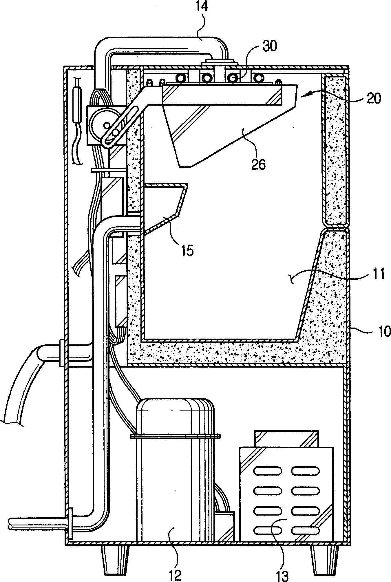
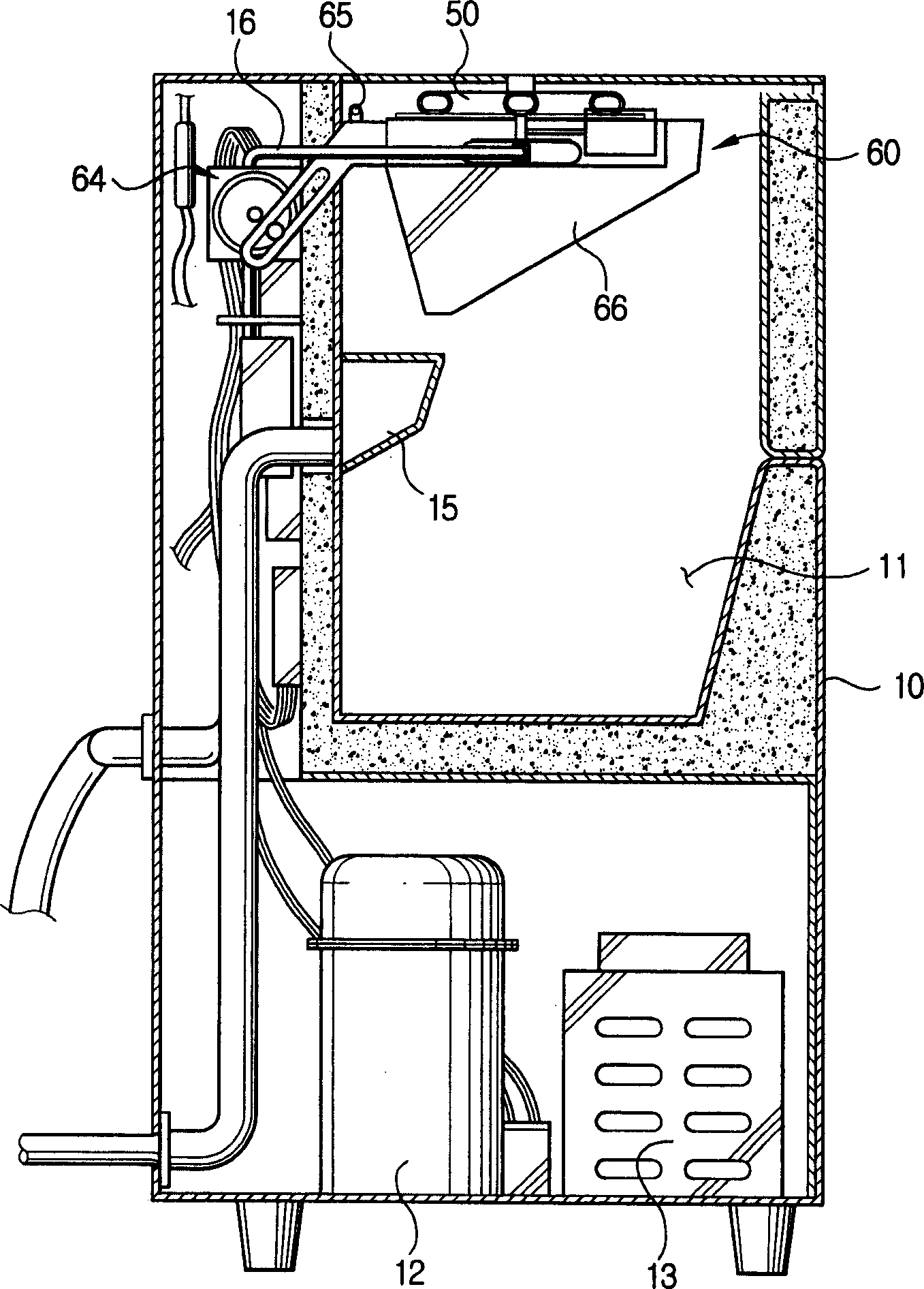
[0028] Such as image 3 and 4 As shown, the ice maker according to the present invention includes: a frame 10 , a freezing device 60 and an air removing device 70 .

[0029] An ice tank 11 is provided in the rack 10 for storing ice cubes formed in the freezer 60 . Below the ice tank 11, a compressor 12 and a condenser 13 are installed, which constitute a cooling or freezing system. A water collecting part 15 is placed on the side of the ice tank 11, which is used to collect unfrozen water.

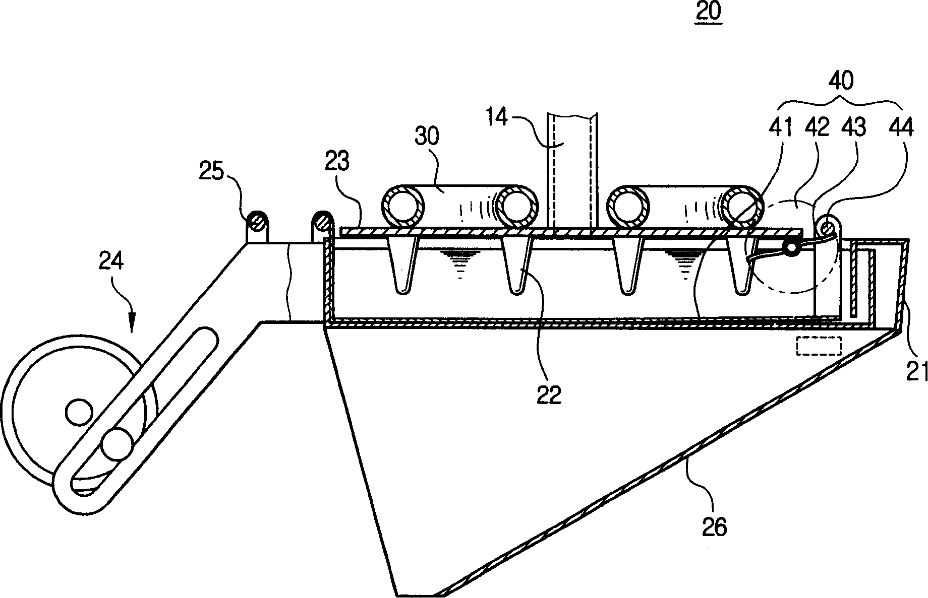
[0030] The freezing device 60 includes a base 61 , a freezing chassis 62 and an evaporator 50 . The base 61 is rotatably mounted on the frame, and it has a plurality of freezing compartments 63 for filling with water to be frozen. The base 61 is rotat...


PUM


Abstract

An ice making machine comprises a housing, an evaporator connected to a freezing system, a base frame having a plurality of freezing cells for being filled with water to be frozen, a freezing base plate provided with the evaporator and freezing fingers formed on the lower surface of the freezing base plate to be dipped into the water supplied to the freezing cells, and an air removing means for pumping the water into the freezing cells to remove air bubbles inside the water, thereby forming clear pieces of ice. The air removing means comprises a water path disposed at the base frame to be connected to the freezing cells, a water pocket connected to the water path and being replenished with water form an external water supply, and a pressing means for repeatedly pressing the water pocket to pump the water of the water pocket into each freezing cell.

Description

technical field [0001] The present invention relates generally to an ice making machine, and more particularly, to an ice making machine capable of reducing ice making time and preventing waste or loss of water needed to freeze. Background technique [0002] Ice machines are commonly used to freeze water to form ice cubes. Ice makers have been proposed to prevent the opacity of ice cubes due to the presence of air bubbles in the freezing water during icing. [0003] figure 1 as well as figure 2 A conventional ice maker as disclosed in US Patent No. 5,425,243 is shown. [0004] Such as figure 1 , 2 As shown, the conventional ice maker includes: a rack 10 , a freezing device 20 and an air removing device 40 . [0005] There is an ice tank 11 in the rack 10 for storing ice cubes formed in the freezer 20 . Below the ice tank 11 a compressor 12 and a condenser 13 are installed. [0006] Such as figure 2 As shown, the freezing device 20 includes: a water pan 21 , a free...

Claims


Application Information

Patent Timeline
Patent Type & Authority Applications(China)
IPC IPC(8): F25C1/22F25C1/00F25C1/08F25C1/12F25C1/18F25C1/20F25C1/24
CPCF25C1/08F25C1/18F25C1/24
Inventor 金五福
Owner SAMSUNG GWANGJU ELECTRONICS CO LTD
Why Eureka
Try Eureka