Apparatus for forming transparent coating and colour imaging apparatus using the same
A transparent coating and equipment technology, which is applied in the field of color imaging equipment, can solve the problems of reduced productivity, enlarged equipment, and inability to form a transparent resin layer uniformly, and achieve the effect of high gloss and smooth surface
- Summary
- Abstract
- Description
- Claims
- Application Information
AI Technical Summary
Problems solved by technology
Method used
Image

Examples
Embodiment 1
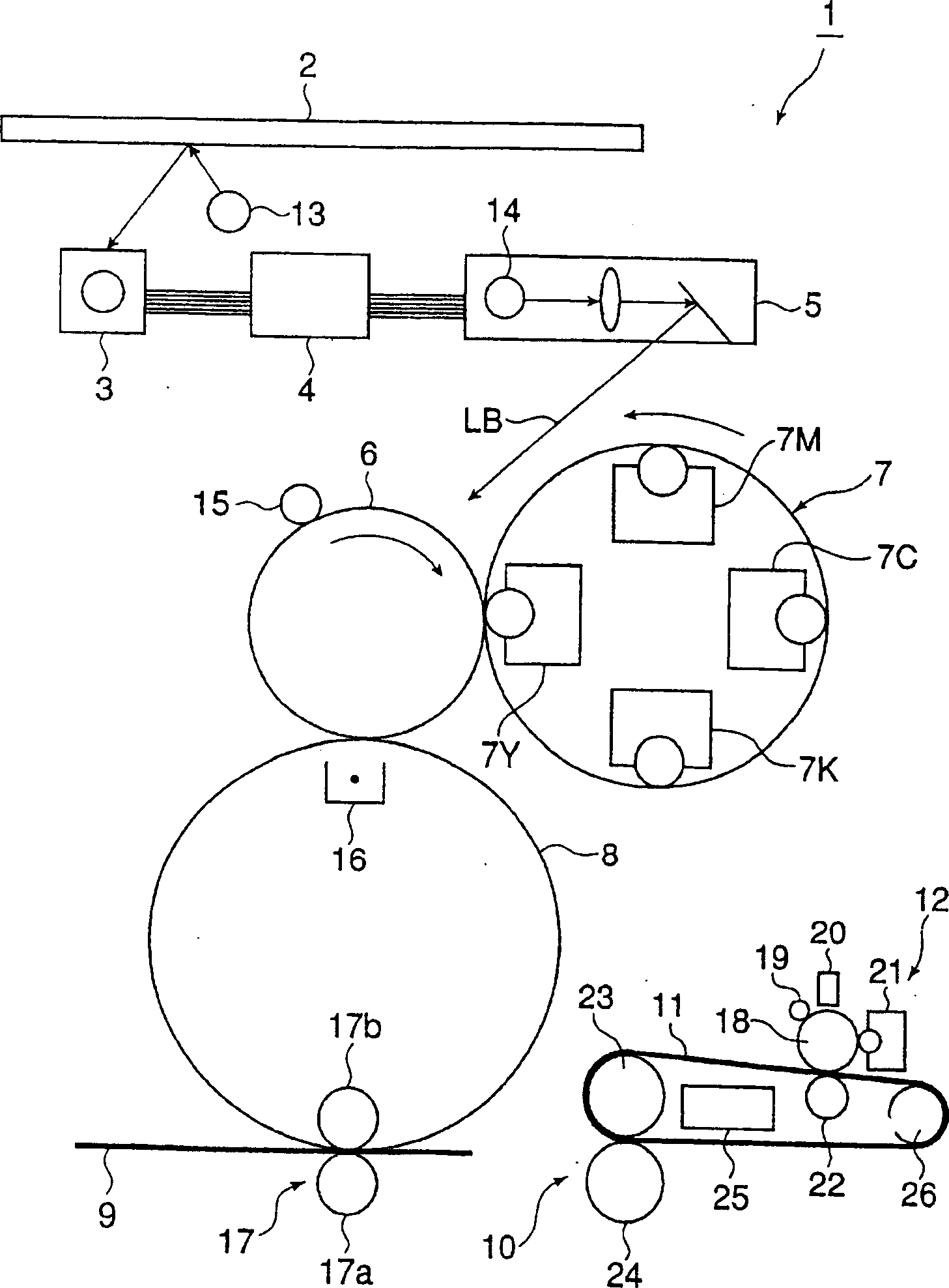
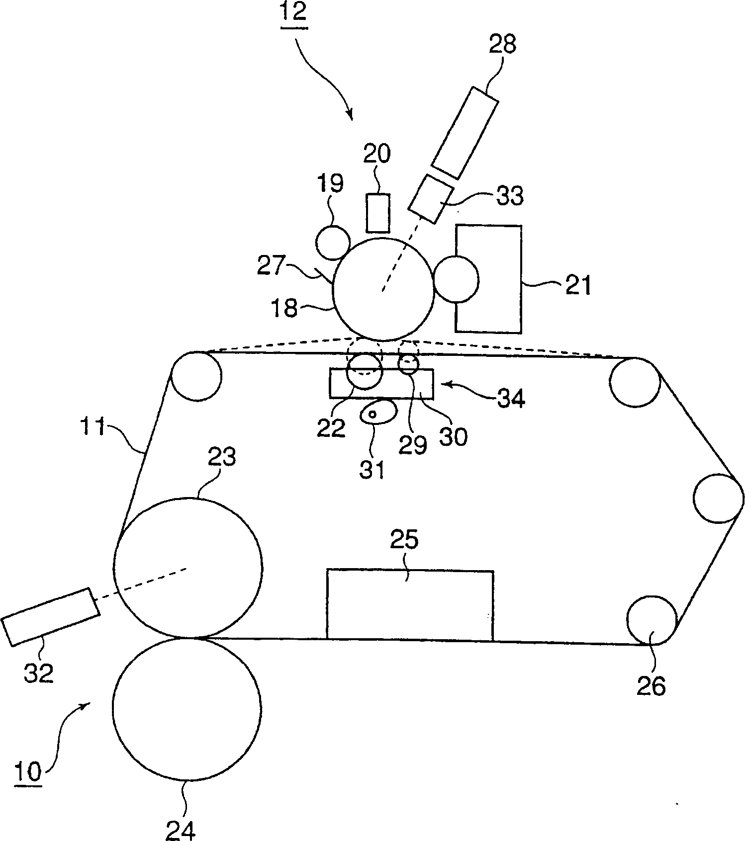
[0128] figure 2 is a view showing the structure of a clear coat forming apparatus provided with a particle layer forming apparatus 12 (thermoplastic particle layer forming apparatus) according to Embodiment 1 of the present invention.
[0129] As the particle layer forming device 12, a thermoplastic particle layer forming device is selected, which includes a photosensitive drum 18, a charging device 19 opposite to the photosensitive drum 18, an exposure device 20, and a device for developing a thermoplastic particle layer. A particle layer developing device 21, and a transfer roller 22 for transferring from the photosensitive drum 18 to the fixing belt 11. As the granular layer developing device 21, a non-contact type one-component developing unit is used. The particle layer developing device 21 negatively charges a particle layer by sandwiching it between a semiconductor developing roller and a silicone rubber blade. AC and DC bias voltages overlapping each other are appli...
Embodiment 2
[0138] Embodiment 2 is described below, and the description of the same components as in Embodiment 1 is omitted.
[0139] In Example 2, in the same manner as in Example 1, when no granular layer is formed, the granular layer forming device 12 shrinks from the fixing belt 11, and when the end of the recording sheet 9 passes through the fixing between the heating roller 23 and the pressure roller 24 The particle layer forming device 12 and the fixing belt 11 contract with each other at the nip portion.
[0140] Figure 5 Among them, (e) represents a change in the running speed of the fixing belt 11, indicating that the speed in the upper direction is accelerated and the speed in the lower direction is decelerated. When the recording sheet 9 enters the fixing nip portion between the heating roller 23 and the pressure roller 24 , the running speed of the fixing belt 11 is reduced, causing the heating roller 23 and the pressure roller 24 to rotate on the recording sheet 9 . When...
Embodiment 3
[0143] Embodiment 3 is described below, and the description of the same components as in Embodiment 1 is omitted.
[0144] In Embodiment 3, there is provided a switching selection mechanism for selecting the driving means for the granular layer forming device or the thermal fixing device by switching at least while the particle layer forming device is forming the particle layer on the fixing belt.
[0145] In Embodiment 3, when the driving means of the granular layer forming device or the thermal fixing device is selected by switching, the granular layer forming device and the thermal fixing device are driven by the same driving means. In this case, as the same driving device for driving the particle layer forming apparatus and the thermal fixing device, a thermal fixing device driving device is used.
[0146] Also, in Embodiment 3, when the thermal fixing device driving device is used as the same driving device that drives the particle layer forming device and the thermal fix...
PUM
 Abstract
Description
Claims
Application Information
 - R&D
- Intellectual Property
- Life Sciences
- Materials
- Tech Scout
- Unparalleled Data Quality
- Higher Quality Content
- 60% Fewer Hallucinations
Browse by: Latest US Patents, China's latest patents, Technical Efficacy Thesaurus, Application Domain, Technology Topic, Popular Technical Reports.
© 2025 PatSnap. All rights reserved.Legal|Privacy policy|Modern Slavery Act Transparency Statement|Sitemap|About US| Contact US: help@patsnap.com