Ultra high speed optical fiber grating sensor demodulating system and its realizing method

A fiber grating and demodulation system technology, which is applied in the fields of optical fiber communication, optical fiber sensing and laser, can solve the problems of demodulation speed limitation, narrow demodulation range, and low resolution, and achieve ultra-high demodulation speed and demodulation Wide-ranging, high-resolution effects

Inactive Publication Date: 2004-05-05
上海紫珊光电技术有限公司
View PDF1 Cites 17 Cited by
  • Summary
  • Abstract
  • Description
  • Claims
  • Application Information

AI Technical Summary

Problems solved by technology

[0008] Although the first three methods have the advantages of high-speed demodulation, the resolution is low and the demodulation range is relatively narrow. The fourth method has a wide demodulation range, but its demodulation speed is limited by the modulation speed of the interferometer. The fifth method costs Too high, and the demodulation speed is not high, currently there are only tens of Hz products

Method used


Image

  • Ultra high speed optical fiber grating sensor demodulating system and its realizing method
  • Ultra high speed optical fiber grating sensor demodulating system and its realizing method
  • Ultra high speed optical fiber grating sensor demodulating system and its realizing method

Examples


Embodiment Construction

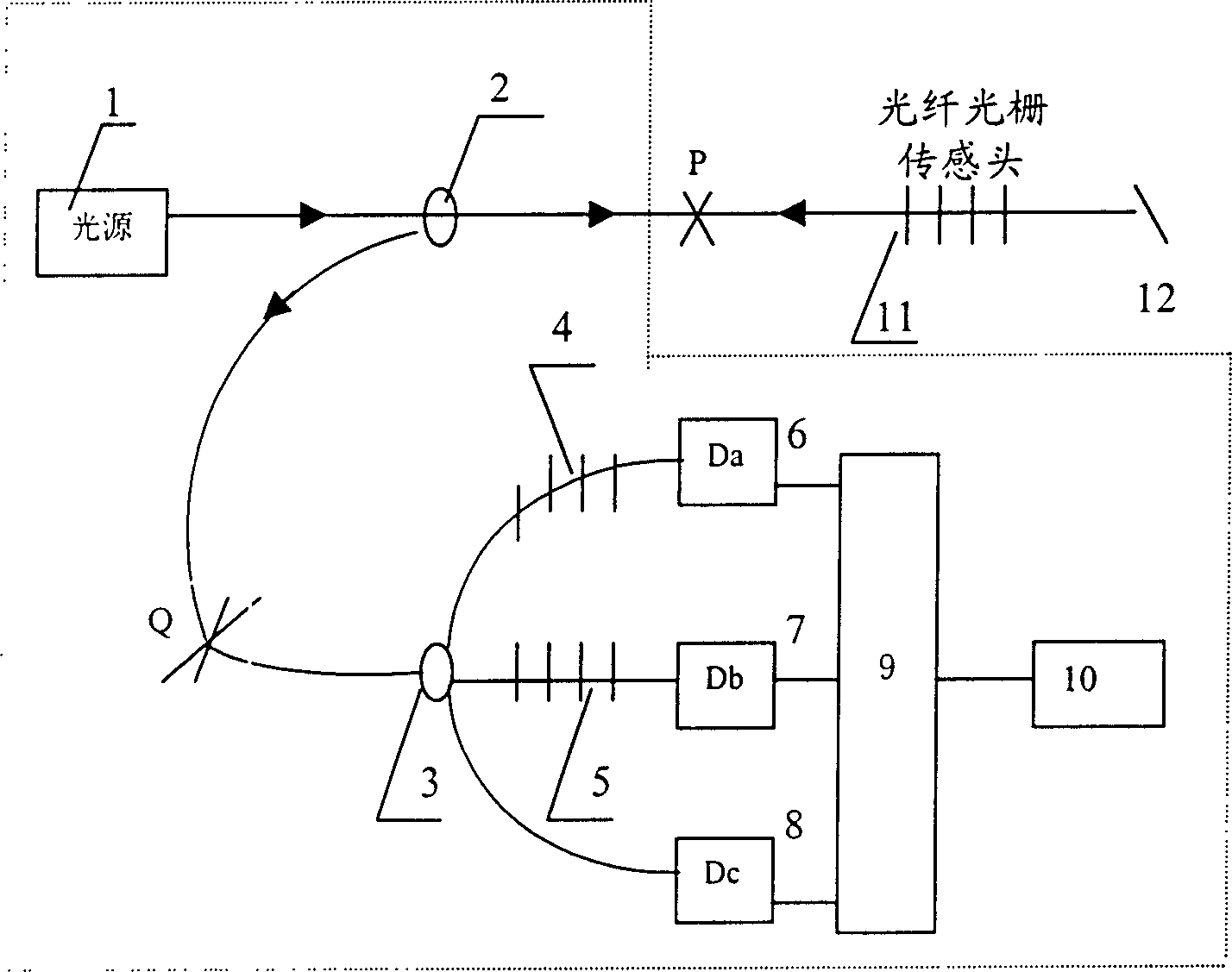
[0036] see figure 1 , figure 1 The dotted box is an embodiment diagram of a typical demodulation system of the present invention.

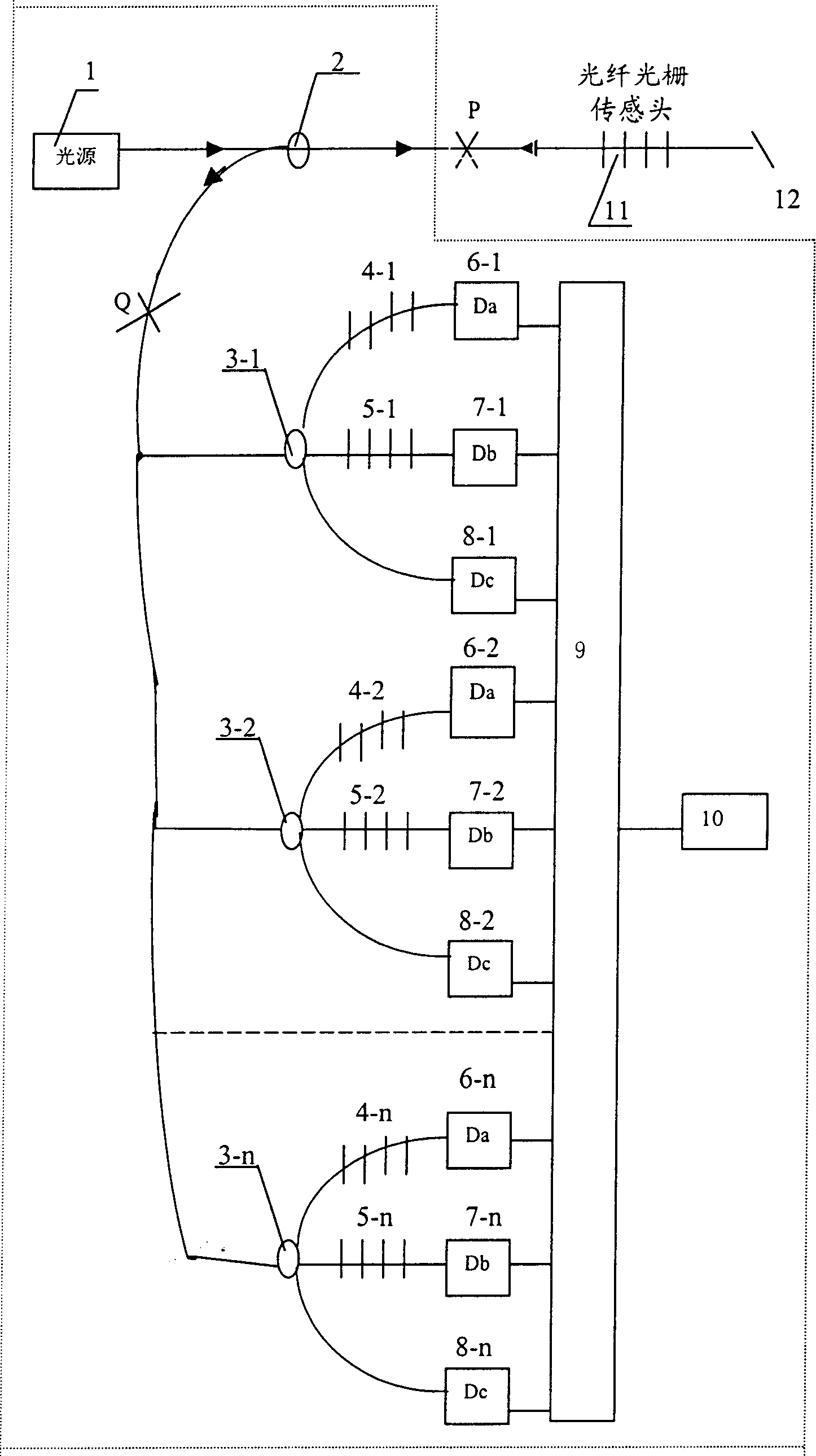
[0037] The light source 1 can be continuous or pulsed. The first coupler 2 is a 2*1 coupler, or a 2*2 coupler or a circulator. This example uses a 2*1 coupler. The second coupler 3 is a 1*3 coupler, or two 2*2 couplers can be connected in series. In this example, a 1*3 coupler is used. The connection point between the first coupler 2 and the second coupler 3 is the Q point.

[0038] The light source 1 passes the light wave through the second coupler 3 to the fiber grating sensor head 11. After the sensor head 11 is subjected to the measured action, the wavelength of the reflected light moves, and then the first coupler 2 and the second coupler coupler Device 3, through optical element (in this embodiment with fiber grating) 4 and optical element (in this embodiment with fiber grating) 5 and monitoring end (optical fiber between the second coupl...


PUM


Abstract

In the system, relations between transmittance and wavelength of two optical elements are sine function with error and cosine function with error respectively. Through processing optical signal power of two optical elements and monitoring end received by detector obtain lookup table about two transmittances and ratio as well as arc tangent function value phi (lambda) of the said ratio and standard wavelength. The said lookup table is stored into memory in demodulation system so as to realize system calibration. Through processing optical signal power of optical fiber grating sensor received by detector obtains the said two transmittances and ratio. Using lookup table in system memory obtains two or more phase values and wavelength values. Then, using linear or non-linear interpolation obtains wavelength value, which is converted to a measured sensing value. The invention possesses features of super high demodulation speed, wide demodulation range, high resolution and low cost.

Description

(1) Technical field [0001] The invention relates to the technical fields of optical fiber communication, optical fiber sensing and laser, in particular to an ultra-high-speed fiber grating sensor demodulation system and its realization method. (2) Background technology [0002] The fiber grating sensor is based on the external action on it, resulting in the change of the refractive index or grating pitch of the grating area, which causes the movement of the reflected wavelength as the sensing mechanism. The essence of its demodulation of the measured signal is the measurement of the wavelength shift. In addition to the traditional scanning spectrometer and scanning interferometer, the existing demodulation systems and methods mainly include: [0003] 1. Based on the linear sideband filter method (US patent 5,729,347) [0004] 2. Coupler method based on wavelength correlation (US Patent 5,882,049) [0005] 3. Based on chirped grating method (US patent 6,335,524) [0006] ...

Claims


Application Information

Patent Timeline
Patent Type & Authority Applications(China)
IPC IPC(8): G02B6/26G02F2/00
Inventor 韦春龙
Owner 上海紫珊光电技术有限公司
Why Eureka
Try Eureka