Large-range high-speed fiber bragg grating sensor demodulation device and demodulation method based on DSP
A technology of fiber grating and demodulation method, which is applied in measurement devices, light demodulation, and optical devices, etc., can solve the problems of fiber grating demodulation system that has not yet been seen, restricts fiber grating sensing, and is difficult to meet vibration and other problems. , to achieve the effect of wide demodulation range, strong anti-interference and wide transmission bandwidth
- Summary
- Abstract
- Description
- Claims
- Application Information
AI Technical Summary
Problems solved by technology
Method used
Image
Examples
Embodiment 1
[0060] Embodiment 1: demodulation device and system implementation
[0061] Such as figure 1 As shown, the broadband light sent by the light source 1 reaches the fiber Bragg grating sensor 3 through the coupler 2, and the reflected light reaches the thin-film filter 4 through the coupler 2, and the output optical power at both ends of the thin-film filter passes through a pair of photodetectors 5 ( Figure 5 6, 7) into electrical signals for signal processing.
[0062] Signal processing and transmission system structure such as Figure 5 Shown:
[0063] 6 and 7 are a pair of low-noise photodetectors (with figure 1 Corresponding to 5 in), 8 and 9 are the pre-logarithmic amplifier AD8304 (the circuit diagram is as follows Image 6 ), 10 is the differential amplifier AD620 (circuit diagram as Figure 7 ), 11 is a low-pass filter circuit (circuit diagram such as Figure 7 ), 12 is the analog / digital converter AD7663 (circuit such as Figure 8 ), 13 is the clock circuit and ...
Embodiment 2
[0070] Embodiment 2: demodulation method and realization
[0071] The demodulation process of the above-mentioned demodulation device is as follows:
[0072] The broadband spectrum is irradiated onto the Bragg FBG sensor, and the part satisfying the Bragg equation (Equation 1) is strongly reflected. The spectrum is transformed through a thin-film filter (device 4), and the modulated narrow-band wave carrying external information is converted into two-way signal light whose optical power varies with wavelength. The introduction of reference light eliminates the influence of light intensity fluctuations caused by light sources and fiber optic connectors on measurement results. The two optical signals are converted into electrical signals by the PIN photodetector, and then converted into digital signals by the A / D conversion circuit with a precision voltage regulator module through logarithmic differential amplification (see formula 3 for the differential amplification result). ...
Embodiment 3
[0076] Embodiment 3: application example
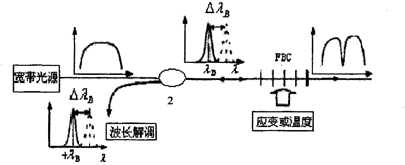
[0077] The demodulation device and method of the invention can be applied to fiber grating stress and temperature sensing. Implant the Bragg fiber grating into the system under test. The temperature or stress of the system changes, or causes the refractive index of the fiber grating to change. Such as figure 1 As shown, the broadband spectral source 1 emits a continuous wavelength spectrum and irradiates it on the Bragg fiber grating sensor. According to the Bragg formula (Equation 1), the reflection wavelength of the grating will change, and the reflection wavelength carries temperature or stress information. A thin-film filter (device 4) is used for wavelength demodulation of the reflected light. The device divides the narrow-band wave into transmission and reflection light, and the introduction of reference light eliminates the influence of light intensity fluctuations caused by light sources and fiber optic connectors on the me...
PUM
 Abstract
Description
Claims
Application Information
 - R&D
- Intellectual Property
- Life Sciences
- Materials
- Tech Scout
- Unparalleled Data Quality
- Higher Quality Content
- 60% Fewer Hallucinations
Browse by: Latest US Patents, China's latest patents, Technical Efficacy Thesaurus, Application Domain, Technology Topic, Popular Technical Reports.
© 2025 PatSnap. All rights reserved.Legal|Privacy policy|Modern Slavery Act Transparency Statement|Sitemap|About US| Contact US: help@patsnap.com


