Large-range high-speed fiber bragg grating sensor demodulation device and demodulation method based on DSP

A technology of fiber grating and demodulation method, which is applied in the direction of measuring device, light demodulation, and optical device, etc. It can solve the problems that the fiber grating demodulation system has not yet been seen, restricts fiber grating sensing, and is difficult to meet vibration. , to achieve the effect of wide demodulation range, strong anti-interference and wide transmission bandwidth

Inactive Publication Date: 2010-01-13
TIANJIN UNIV
View PDF0 Cites 14 Cited by
  • Summary
  • Abstract
  • Description
  • Claims
  • Application Information

AI Technical Summary

Problems solved by technology

[0005] At present, fiber grating demodulation equipment mostly uses tunable filters, and the demodulation speed is low, generally not greater than 200Hz, which is difficult to meet the requirements of real-time high-speed sampling occasions such as vibration and geological monitoring
Demodulation with edge filter only uses its linear demodulation part, and the demodulation range is narrow
A fiber grating demodulation system that can guarantee high demodulation rate and wide response range at the same time has not yet been seen, which has become a prominent problem restricting the further development of fiber grating sensing

Method used


Image

  • Large-range high-speed fiber bragg grating sensor demodulation device and demodulation method based on DSP
  • Large-range high-speed fiber bragg grating sensor demodulation device and demodulation method based on DSP
  • Large-range high-speed fiber bragg grating sensor demodulation device and demodulation method based on DSP

Examples


Embodiment 1

[0059] Embodiment 1: demodulation device and system implementation

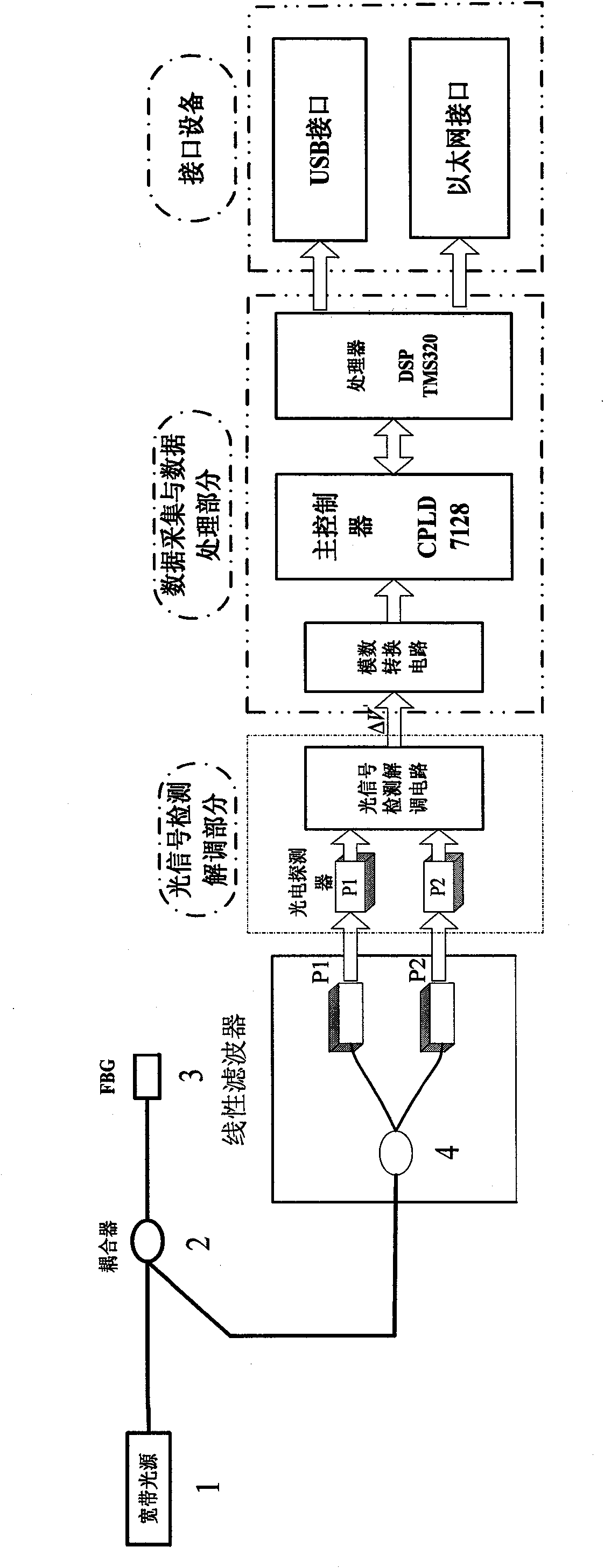
[0060] Such as figure 1 As shown, the broadband light sent by the light source 1 reaches the fiber Bragg grating sensor 3 through the coupler 2, and the reflected light reaches the thin-film filter 4 through the coupler 2, and the output optical power at both ends of the thin-film filter passes through a pair of photodetectors 5 ( Figure 5 6, 7) into electrical signals for signal processing.

[0061] Signal processing and transmission system structure such as Figure 5 Shown:

[0062] 6 and 7 are a pair of low-noise photodetectors (with figure 1 Corresponding to 5 in), 8 and 9 are the pre-logarithmic amplifier AD8304 (the circuit diagram is as follows Image 6 ), 10 is the differential amplifier AD620 (circuit diagram as Figure 7 ), 11 is a low-pass filter circuit (circuit diagram such as Figure 7 ), 12 is the analog / digital converter AD7663 (circuit such as Figure 8 ), 13 is the clock circuit and ...

Embodiment 2

[0069] Embodiment 2: demodulation method and realization

[0070] The demodulation process of the above-mentioned demodulation device is as follows:

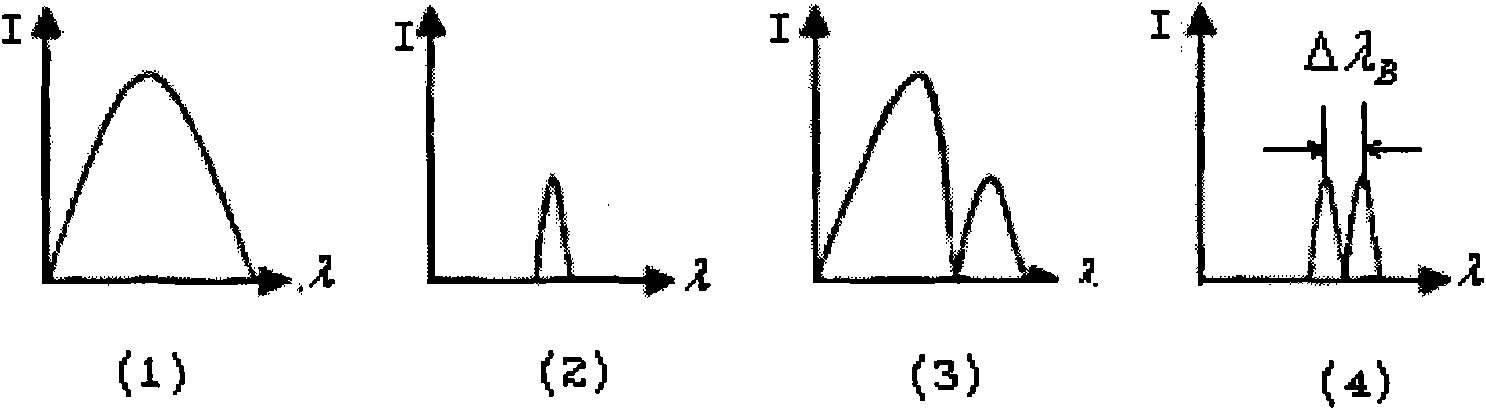
[0071] The broadband spectrum is irradiated onto the Bragg FBG sensor, and the part satisfying the Bragg equation (Equation 1) is strongly reflected. The spectrum is transformed through a thin-film filter (device 4), and the modulated narrow-band wave carrying external information is converted into two-way signal light whose optical power varies with wavelength. The introduction of reference light eliminates the influence of light intensity fluctuations caused by light sources and fiber optic connectors on measurement results. The two optical signals are converted into electrical signals by the PIN photodetector, and then converted into digital signals by the A / D conversion circuit with a precision voltage regulator module through logarithmic differential amplification (see formula 3 for the differential amplification result). ...

Embodiment 3

[0075] Embodiment 3: application example

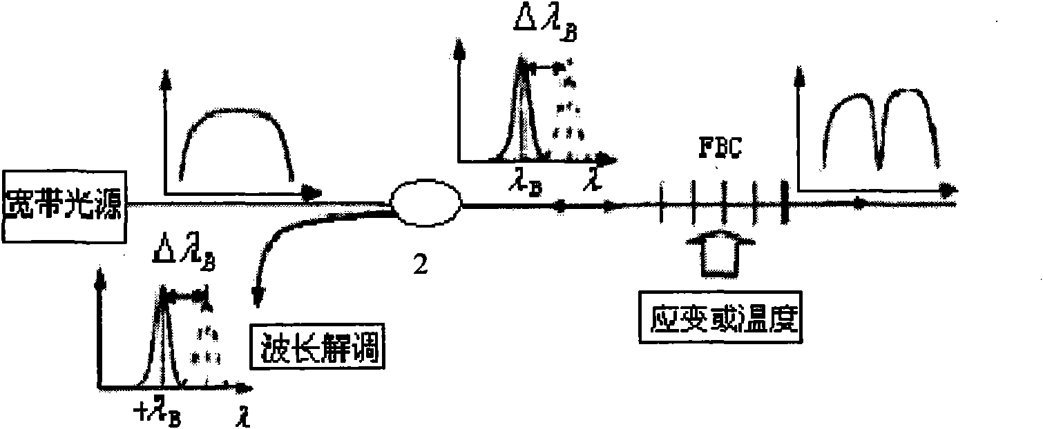
[0076] The demodulation device and method of the invention can be applied to fiber grating stress and temperature sensing. Implant the Bragg fiber grating into the system under test. The temperature or stress of the system changes, or causes the refractive index of the fiber grating to change. Such as figure 1 As shown, the broadband spectral source 1 emits a continuous wavelength spectrum and irradiates it on the Bragg fiber grating sensor. According to the Bragg formula (Equation 1), the reflection wavelength of the grating will change, and the reflection wavelength carries temperature or stress information. A thin-film filter (device 4) is used for wavelength demodulation of the reflected light. The device divides the narrow-band wave into transmission and reflection light, and the introduction of reference light eliminates the influence of light intensity fluctuations caused by light sources and fiber optic connectors on the me...


PUM


Abstract

The invention discloses a large-range high-speed fiber bragg grating sensor demodulation device and a demodulation method based on DSP, using the membrane filter technology to realize signal demodulation. A DSP special processing circuit is used for carrying out high-speed real-time signal acquisition and processing on the signal. The device adopts the method of logarithmic amplification plus differential amplification methods to obtain the ratio between the signals of two paths. The DSP is used to carry out high-speed real-time signal acquisition and processing at the rear end, the sampling result is substituted to a nonlinear fitted curve to obtain a strain value, and the result is directly transmitted to a computer under the control of the CPLD via an interface. Or, a special USB interface is controlled by the CPLD for transmitting the signals. The invention can carry out dynamic and static measurement in real time, the measurement speed is fast and the sensitivity is high, and the invention has the advantages of instantaneity and high speed performance. Processing data can be transmitted to the computer via two transmission modes of the USB interface and a network cable, support plug and play, and can realize long distance transmission, thus facilitating users with different use demands.

Description

【Technical field】: [0001] The invention relates to various DSP-based optical fiber grating sensing fields, especially a large-range high-speed demodulation method and a demodulation device. 【Background technique】: [0002] The Fiber Bragg Grating (FBG) sensor is currently the most widely used fiber Bragg grating sensor. In the entire length of the fiber Bragg grating, the period and refractive index are uniform, and the Bragg resonance wavelength λ B Satisfy: [0003] lambda B =2nΛ(1) [0004] In the formula, Λ is the grating period, and n is the effective refractive index of the fiber core. External disturbances to be measured, such as strain, will cause changes in the refractive index and period of the FBG, thereby causing the Bragg reflection wavelength of the FBG to shift. The change information to be measured can be obtained by measuring the drift of the wavelength. [0005] At present, fiber grating demodulation equipment mostly uses tunable filters, and the demod...

Claims


Application Information

Patent Timeline
Patent Type & Authority Applications(China)
IPC IPC(8): G01D5/353G02F1/35G02F2/00G01K11/32G01L1/24G01B11/16G01K11/3206
Inventor 刘铁根江俊峰何萌邓集杰韩憬李磊
Owner TIANJIN UNIV
Why Eureka
Try Eureka