Torque beam suspension

A torque beam and suspension technology, which is applied in the direction of suspension, elastic suspension, transportation and packaging, etc., can solve the problems of difficult torsion deformation of torque beams, increased welding costs, and enlarged relative ends, etc., to increase toe-in rigidity , Improve the effect of welding accuracy

Inactive Publication Date: 2004-05-12
HONDA MOTOR CO LTD +1
View PDF0 Cites 16 Cited by
  • Summary
  • Abstract
  • Description
  • Claims
  • Application Information

AI Technical Summary

Problems solved by technology

[0004] However, in the case of increasing the longitudinal width of the opposite ends of the torque beam to increase the welding length, there arises a problem that the opposite ends of the torque beam become larger, thereby not only causing an increase in material cost, but also increasing the welding length. Also leads to increased welding co

Method used


Image

  • Torque beam suspension
  • Torque beam suspension
  • Torque beam suspension

Examples


Example Embodiment

[0038] Will now refer to Figure 1-10 The first embodiment of the present invention will be described.
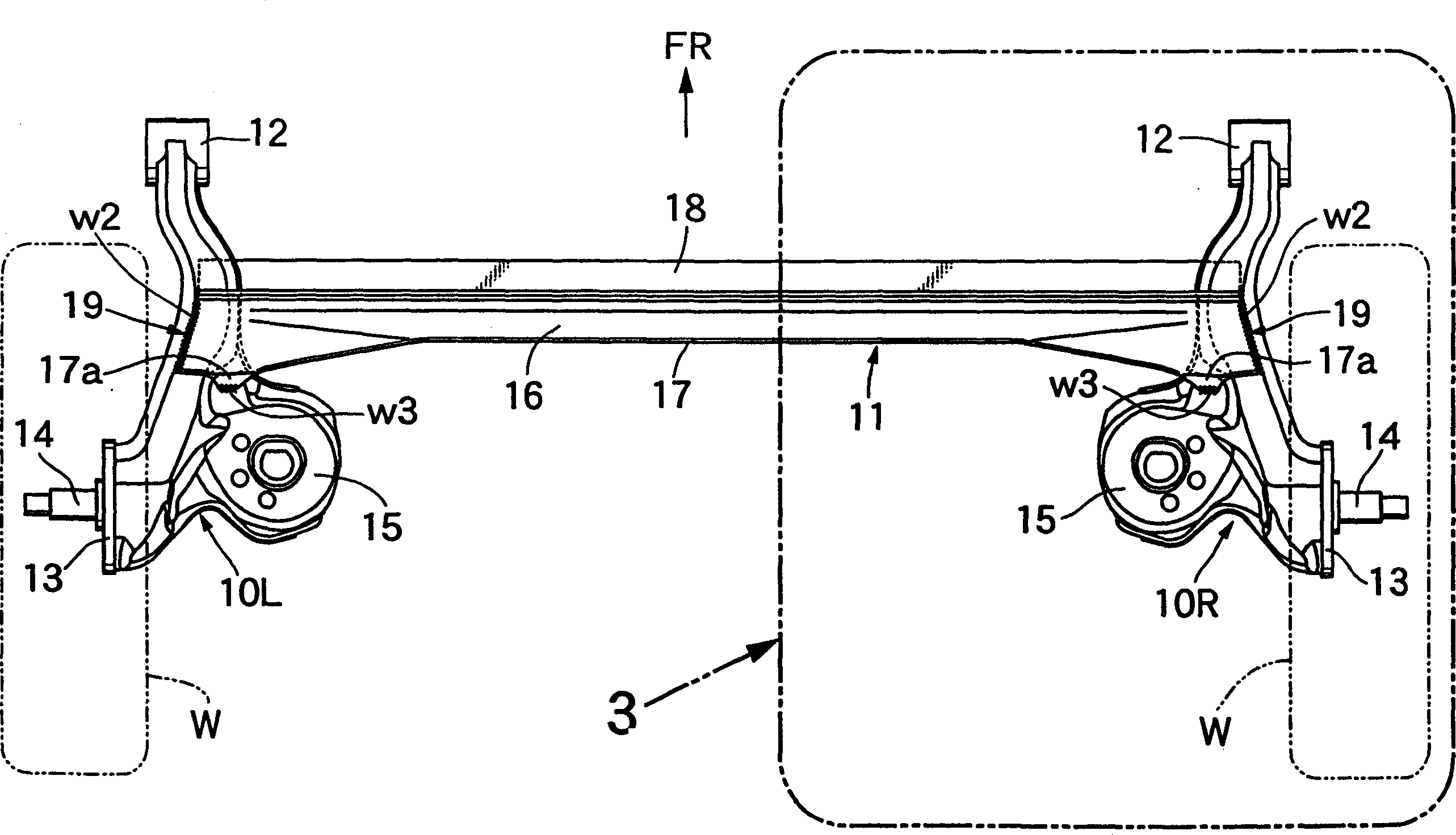
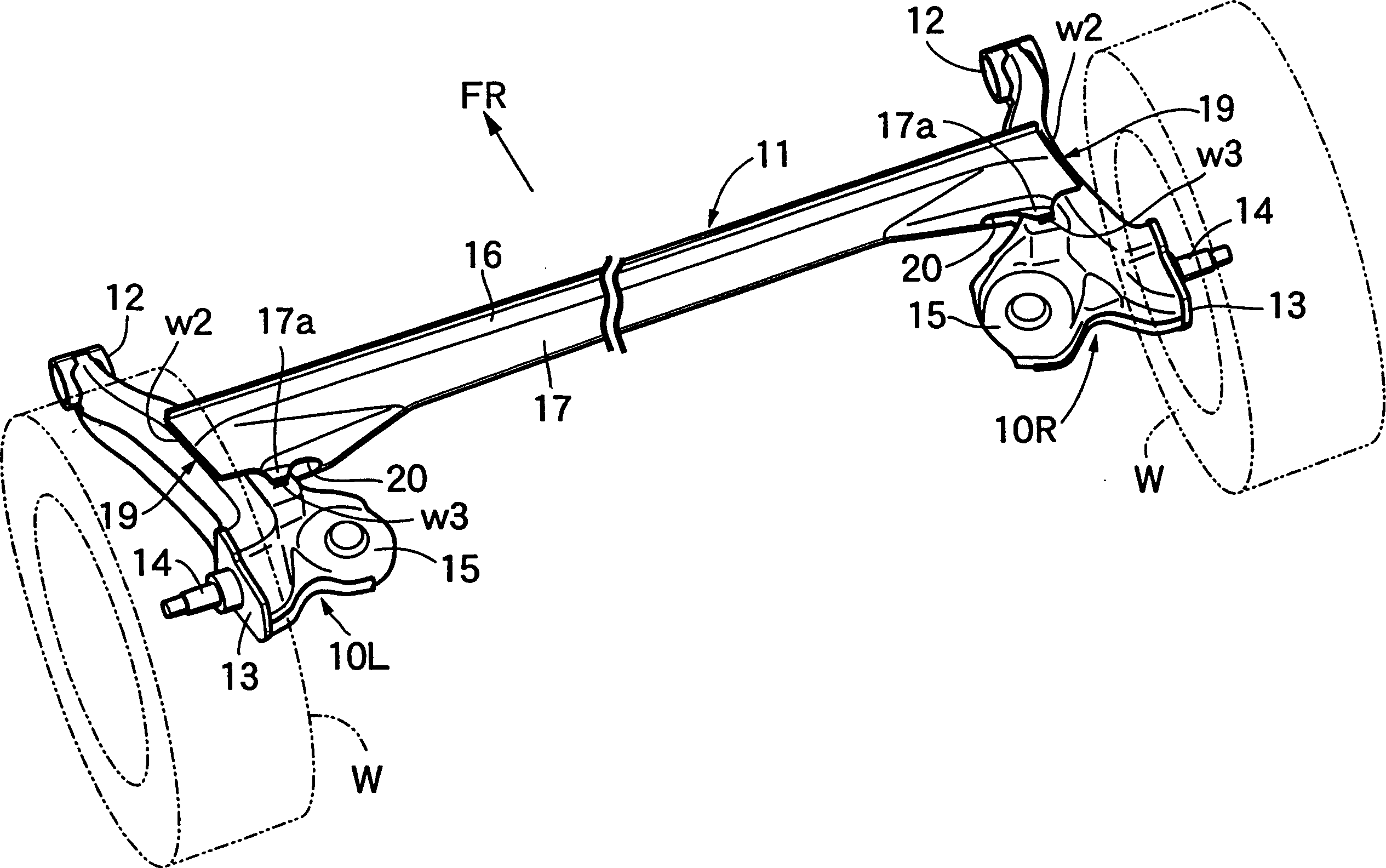
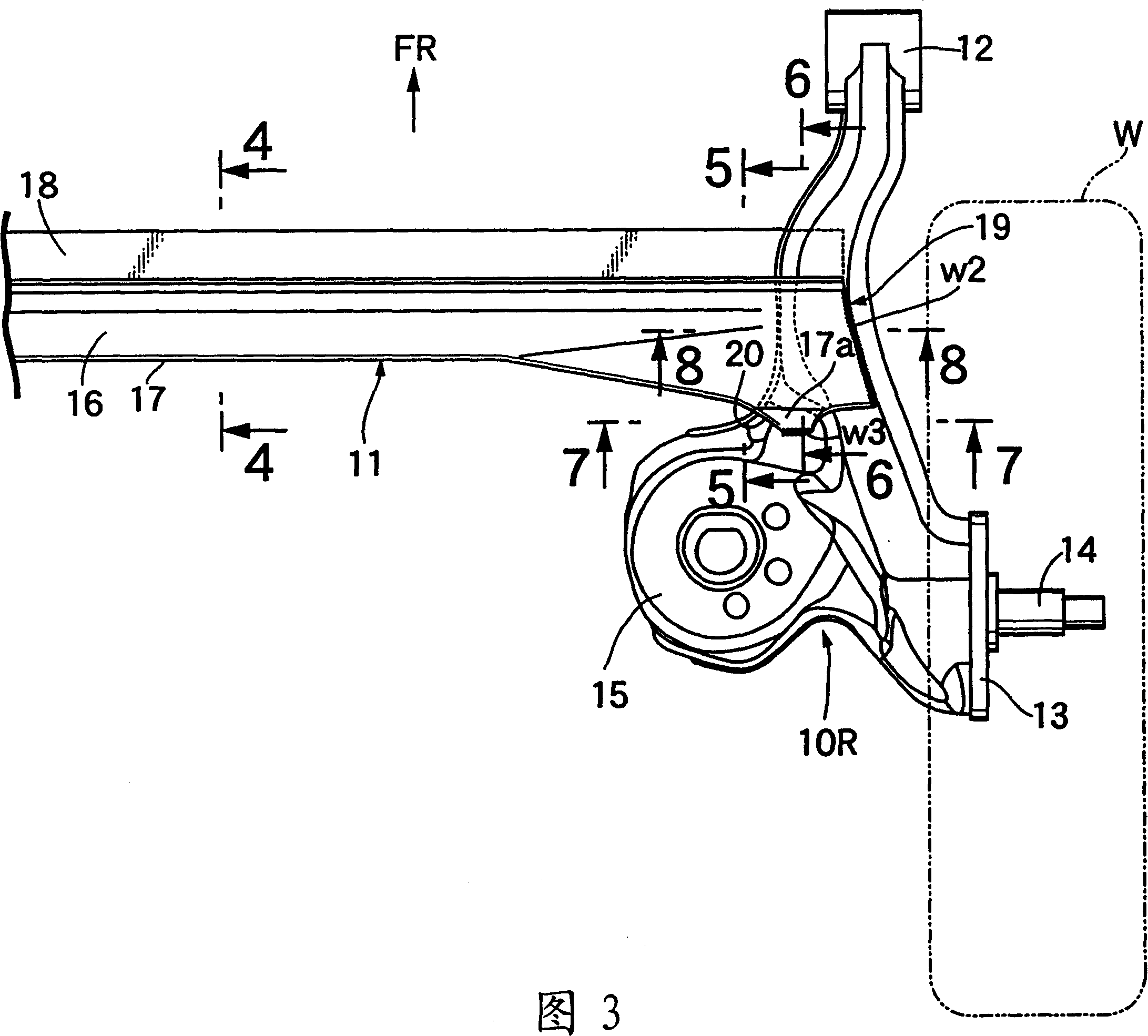
[0039] As in figure 1 with 2 As shown in the figure, the torque beam type suspension for the rear wheel of a car includes left and right trailing arms 10L and 10R extending in the longitudinal direction of the vehicle body, and a torque extending in the transverse direction and connecting the left and right trailing arms 10L and 10R to each other. Beam 11. The cylindrical trailing arm supports 12, 12 are welded to the front ends of the trailing arms 10L and 10R, and are hingedly supported by rubber sleeve joints (not shown) installed in the trailing arm supports 12, 12 to perform on the vehicle body. Vertical swing movement. The left and right rear wheels W, W are rotatably supported on shafts 14, 14 which are fixed to shaft support plates 13, 13 welded to the outer ends of the rear portions of the trailing arms 10L and 10R. Spring seats 15, 15 for supporting the lower ends of...


PUM


Abstract

To suppress increase in size of both end parts of a torsion beam to the minimum extent to reduce material cost and welding cost and increase effective length of the torsion beam capable of being twisted and deformed to ensure durability of a welded part. A torsion beam type suspension is constituted by connecting connection parts 19 at both ends of the torsion beam 11 having U-shaped cross section and extending in the right and left directions of a vehicle body with trailing arms 10L, 10R on the left and right sides extending in the forward and backward directions of the vehicle body and swinging vertically. The connection part 19 is provided with a slit 20 which is formed on a longitudinal wall 17 of the torsion beam 11 and extends in the left and right directions and whose one end is opened and upper and lower flanges 17a overhanging in the forward and backward directions from upper and lower fringe parts of the slit 20. While the slit 20 is fitted into the trailing arms 10L, 10R, outer end fringes of an upper wall 16 and a lower wall and the upper and lower flanges 17a are welded on the trailing arms 10L, 10R. (C)2004,JPO.

Description

technical field [0001] The present invention relates to a torque beam type suspension comprising: left and right trailing arms extending in the longitudinal direction of a vehicle body for vertical swing motion; and a torque beam extending in a transverse direction of the vehicle body and having a U-shape section, and has an upper wall, a vertical wall and a lower wall connected to each other, and connecting portions at opposite ends of the torque beam are connected to the left and right trailing arms. Background technique [0002] Japanese Patent Application Laid-Open No. 2000-94917 discloses a conventional torsion beam type suspension. [0003] The opposite ends of the torque beam of this torsion beam suspension are connected to the longitudinal middle portions of the left and right trailing arms by welding, but when the torque beam is subjected to torsional deformation due to the difference between the angles of the vertical swing motion of the left and right trailing arm...

Claims


Application Information

Patent Timeline
IPC IPC(8): B60G9/04
Inventor 植森康祐中村忠能井上满堀内清志
Owner HONDA MOTOR CO LTD
Why Eureka
Try Eureka