Single spindle driven multiple twisting frame

A drive-type, twisting machine technology, used in spinning machines, continuous winding spinning machines, textiles and papermaking, etc., can solve problems such as reduced spindle stability, longer distance, and increased twisting unit height. , to achieve stable and high-speed rotation, the effect of improving efficiency

Inactive Publication Date: 2004-05-12
MURATA MASCH LTD
View PDF1 Cites 0 Cited by
  • Summary
  • Abstract
  • Description
  • Claims
  • Application Information

AI Technical Summary

Problems solved by technology

[0013] Although it is possible to form a supply path for lubricating oil on the supporting part that supports the spindle shaft so that the lubricating oil can be supplied from the outside while the spindle shaft is supported by bearings, in the structure where the spindle shaft is directly driven by the motor, the If the supply path of lubricating oil is formed above the bearing, the distance from the motor to the rotating disk above the motor will become longer, the height of the twisting unit will increase, and the stability of the spindle shaft at high speed rotation will decrease.

Method used


Image

  • Single spindle driven multiple twisting frame
  • Single spindle driven multiple twisting frame
  • Single spindle driven multiple twisting frame

Examples


Embodiment Construction

[0051] Embodiments of the present invention will be described in detail below with reference to the accompanying drawings.

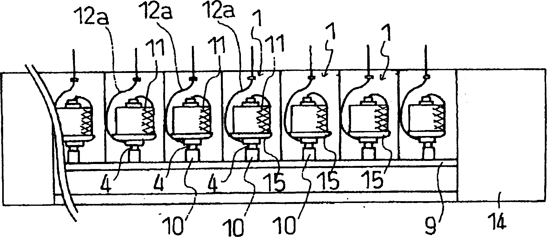
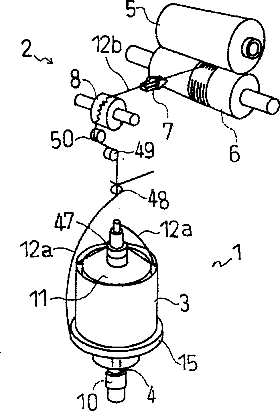
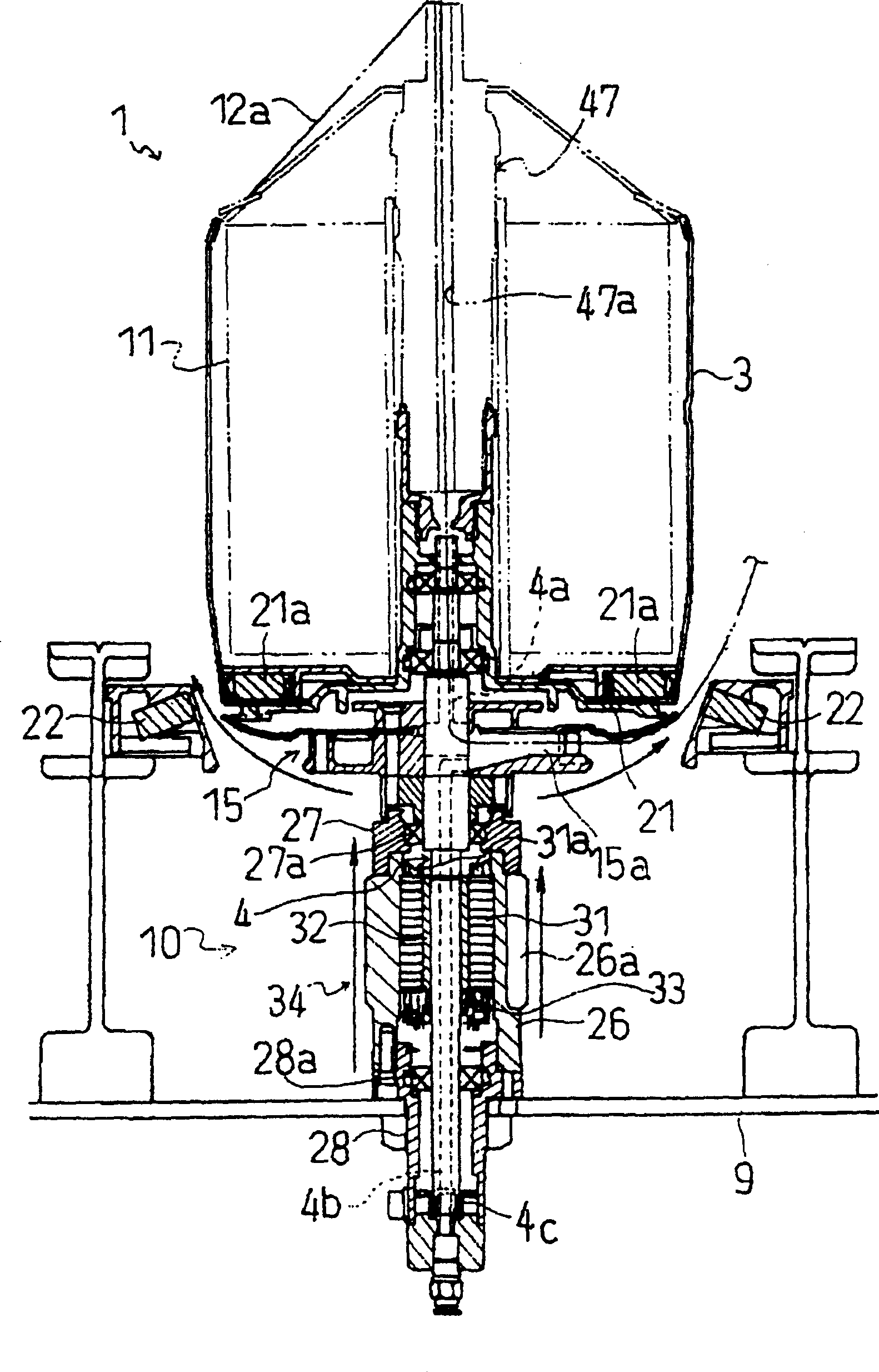
[0052] A brief structure of the single-spindle-driven multiple twister of the present invention will be described below. exist figure 1 Among them, a plurality of twisting units 1 of single-spindle-driven multiple twisting machines are arranged side by side. One spindle shaft 4 that is arranged on each twisting unit 1 and the rotating disk 15 that is positioned at the upper end of this spindle shaft 4 can rotate together, and this spindle shaft 4 is driven to rotate by drive motor 10, thereby makes rotating disk 15 rotate together, Wherein the driving motor 10 is a motor that is respectively arranged on each twisting unit 1 . The rotating disk 15 is disposed above the driving motor 10 , and the twisting unit 1 is supported by the bracket 9 below the driving motor 10 .

[0053] The rotary disk 15 is driven to rotate by the spindle shaft 4 , thereby twi...


PUM


Abstract

The present invention provides an individual-spindle-drive type multiple twister having a motor to directly rotate a spindle shaft of a twisting unit. A bearing support portion for rotatably supporting the spindle shaft via a bearing is formed on the housing of the motor with a stator fixed thereto. Each bearing support member (27, 28; 77, 78) has a lubricating oil supply port (26c, 27c; 76c, 77c) for externally supplying a lubricating oil to the bearings (27a, 28a; 77a, 78a) and a lubricating oil passage (26d, 27d; 76d, 77d) that guides the lubricating oil from the lubricating oil supply port to the bearing, and the lubricating oil passage is located along the outer circumference of the bearing. Thus, the lubricating oil can be externally supplied while the spindle shaft is being supported, thereby simplifying the lubricating oil supply operation and enabling the individual-spindle-drive type multiple twister to be more compact. In addition, the lubricating oil can be easily supplied to the bearing while keeping the height of the twisting unit to a minimum (Fig. 4).

Description

[0001] The present invention is a divisional application of Chinese patent application No. 99109776.9 technical field [0002] The present invention relates to a single-spindle-driven multi-twister machine, which twists a raw yarn multiple times within one rotation of a spindle shaft, and the spindle shaft (spindle shaft) is directly driven to rotate by a motor. Background technique [0003] Existing multi-twisting machines twist the original yarn multiple times within one revolution of a spindle shaft being driven. A twisting machine is known in which a driving belt winds and rotates a plurality of spindles arranged side by side, and simultaneously drives a plurality of spindles by the driving belt. [0004] In such a belt-driven simultaneous drive type multiple twister, the drive belt is pressed against the spindle shaft and is driven under the condition that a radial force is applied to the bearing portion of the spindle shaft, causing a large twist. Noise, and because o...

Claims


Application Information

Patent Timeline
Patent Type & Authority Applications(China)
IPC IPC(8): D01H7/86D01H1/10D01H1/16D01H1/244D01H7/88
CPCD01H1/16D01H1/244D01H7/88D01H7/86
Inventor 木村辰夫梅冈利成
Owner MURATA MASCH LTD
Why Eureka
Try Eureka