Waste gas pipeline with dust accumulation prevention mechanism for catalytic combustion equipment
A waste gas pipeline and catalytic combustion technology, which is applied in the direction of combustion method, combustion type, lighting and heating equipment, etc., can solve the problems of inability to clean up harmful substances, reduce the safety of catalytic combustion equipment, and reduce the service life of exhaust gas pipelines, so as to avoid deposition Hazards, improving cleaning efficiency and cleaning effect, and improving the effect of service life
- Summary
- Abstract
- Description
- Claims
- Application Information
AI Technical Summary
Problems solved by technology
Method used
Image
Examples
Embodiment 1
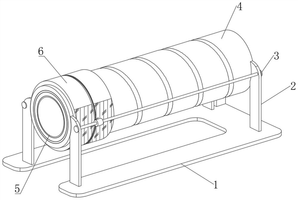
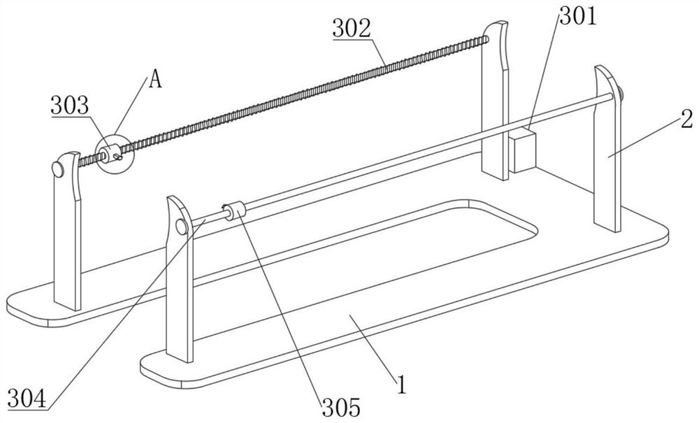
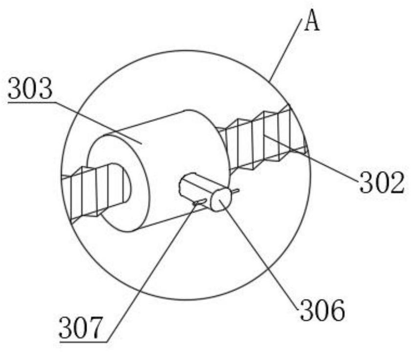
[0046] see Figure 1-10 , an exhaust gas pipeline with a dust-proof mechanism for catalytic combustion equipment, including an exhaust gas pipeline 5 installed on the upper end of a base 1, two sets of support frames 2 are fixedly connected to the upper end of the base 1, and sets of sleeves are fixedly connected between the two sets of support frames 2 The pipe sheath 4 on the outside of the exhaust gas pipe 5, the left end of the pipe sheath 4 is rotatably connected with a semi-magnetic rotating sleeve 6, and the upper end of the support frame 2 is provided with a power assembly 3 matching the semi-magnetic rotating sleeve 6, and the semi-magnetic rotating sleeve 6 Composite semicircular plastic material and semicircular strong magnet; see Figure 4 , the exhaust gas pipeline 5 includes a supporting outer layer 501, and the inner end of the supporting outer layer 501 is fixedly connected with a plurality of vibrating magnetic boxes 502 matched with the semi-magnetic rotating...
Embodiment 2
[0057] see Figure 1-10 , where the same or corresponding components as those in Embodiment 1 use the corresponding reference numerals as in Embodiment 1, and for the sake of simplicity, only the differences from Embodiment 1 will be described below. The difference between this embodiment 2 and embodiment 1 is: please refer to Figure 5 , a plurality of gas detection probes are fixedly installed on the inner side of the supporting outer layer 501, and the gas detection probes are located in the gap between the two vibrating magnetic boxes 502, the output ends of the gas detection probes are connected with transmission wires, and the transmission wires extend to the outside of the connecting plate 504, and Electrically connected with the device controller. After the elastic inner layer 503 is damaged, the exhaust gas will permeate between the supporting outer layer 501 and the vibrating magnetic box 502, and the leaking gas will be detected effectively through the gas detectio...
PUM
 Abstract
Description
Claims
Application Information
 - R&D
- Intellectual Property
- Life Sciences
- Materials
- Tech Scout
- Unparalleled Data Quality
- Higher Quality Content
- 60% Fewer Hallucinations
Browse by: Latest US Patents, China's latest patents, Technical Efficacy Thesaurus, Application Domain, Technology Topic, Popular Technical Reports.
© 2025 PatSnap. All rights reserved.Legal|Privacy policy|Modern Slavery Act Transparency Statement|Sitemap|About US| Contact US: help@patsnap.com


