Fuel supply system
A fuel supply system and fuel supply technology, applied in charging systems, liquid fuel feeders, engine components, etc., can solve problems such as difficulty in identifying filter elements, fatal blockage of filter elements, and user engine failures.
- Summary
- Abstract
- Description
- Claims
- Application Information
AI Technical Summary
Problems solved by technology
Method used
Image
Examples
no. 1 example
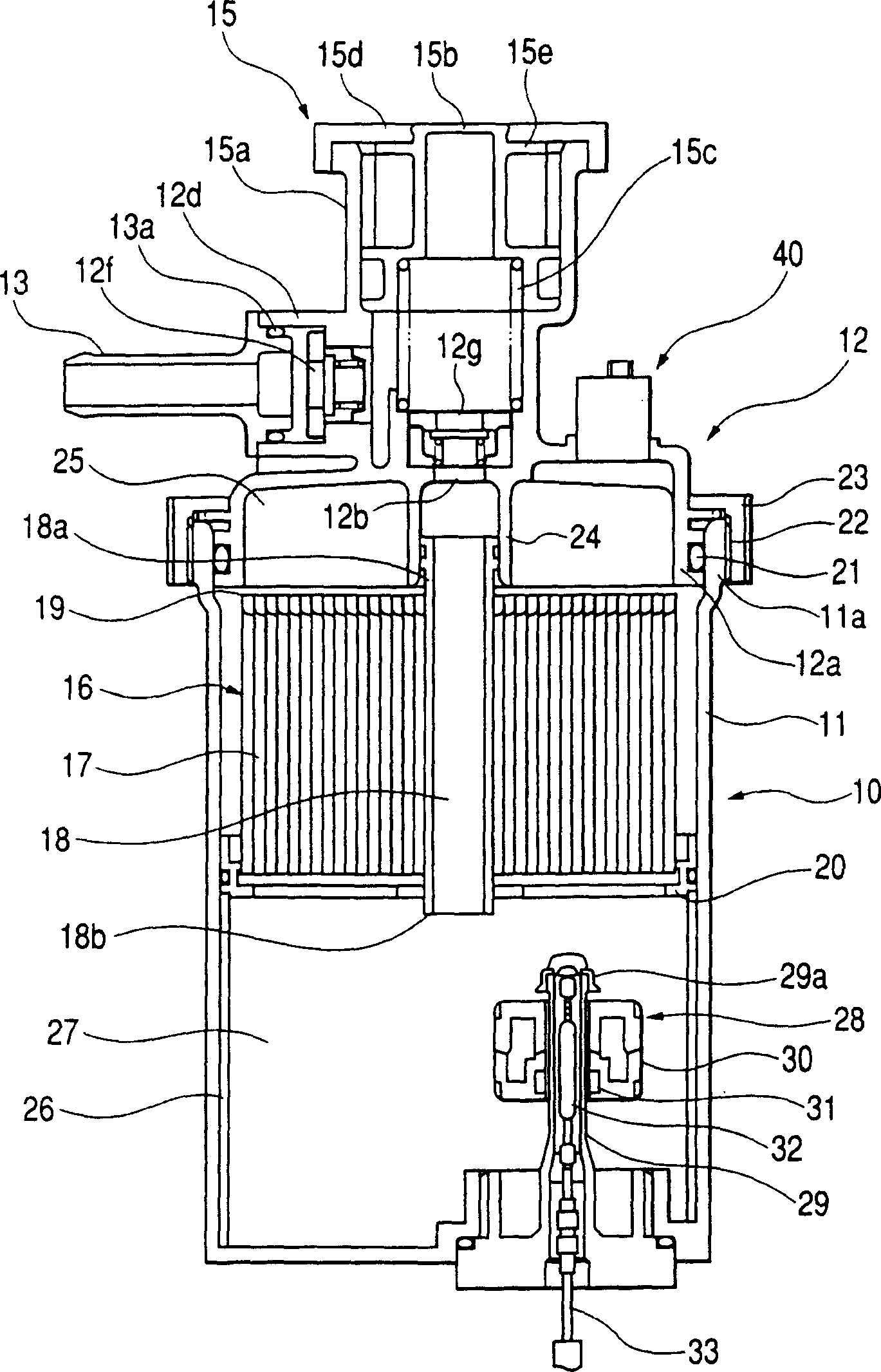
[0082] figure 1 It is a cross-sectional view showing the diesel filter and the clogging detection sensor, where the sensor is provided on the cover of the diesel filter. figure 2 It is an enlarged cross-sectional view showing the arrangement of the jam detection sensor.
[0083] The diesel filter 10 includes: a housing member, which is composed of a cylindrical housing 11 with a closed bottom, the housing 11 defining an outer wall of the diesel filter 10; and a cover 12, which is detachably connected to the housing 11 On the upper open end. The cover 12 is a part formed of resin, and a fuel supply pipe fixing portion 12d and a fuel discharge pipe fixing portion (not shown) are formed on the cover. The gasket 13a is connected to the end of the fuel supply pipe 13, and the fuel supply pipe 13 is integrally connected to the fuel supply pipe fixing portion 12d. Likewise, a fuel discharge pipe (not shown) is connected to the fuel discharge pipe fixing part.
[0084] In addition, whe...
no. 2 example
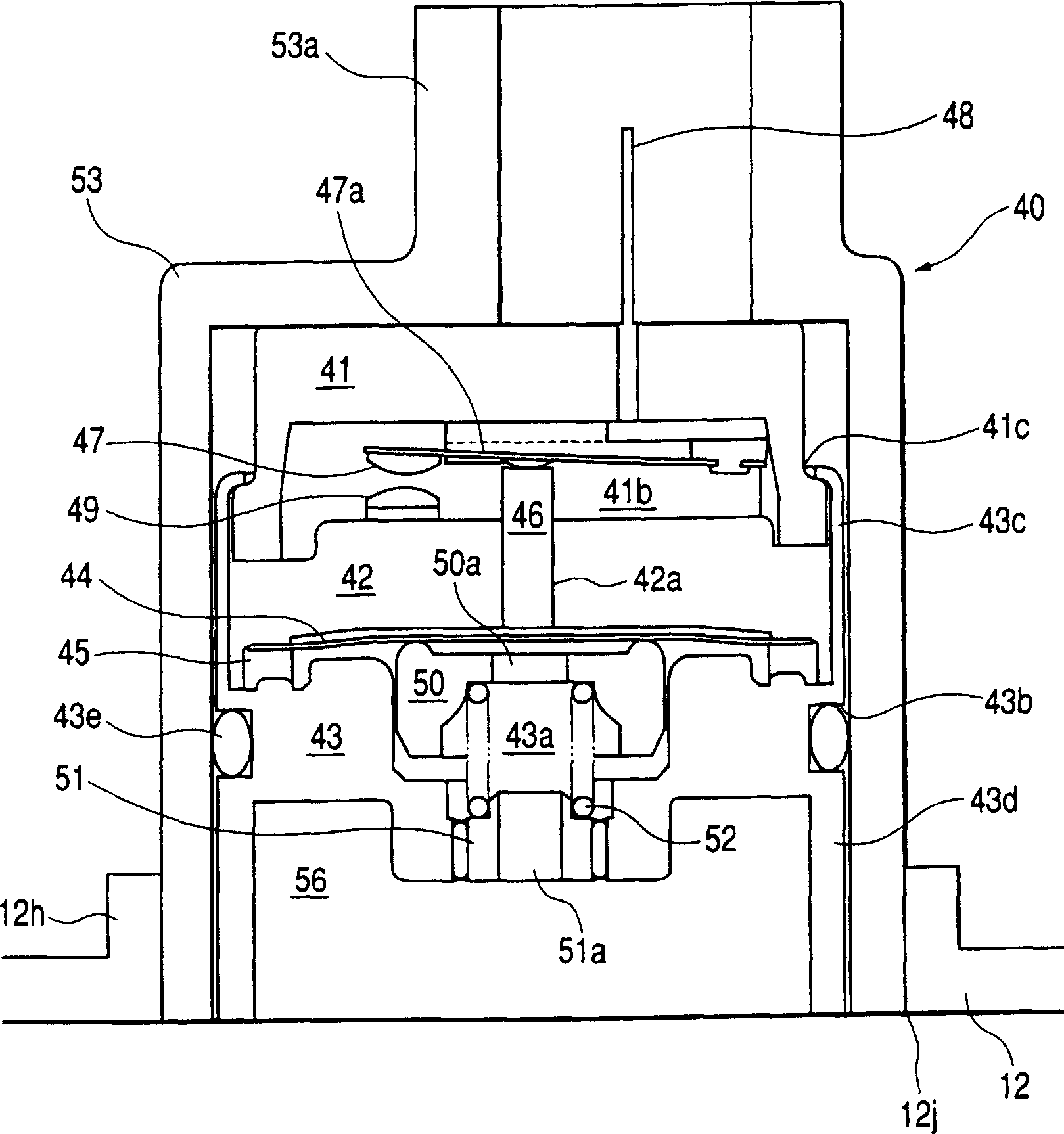
[0110] Figure 5 It is an enlarged cross-sectional view showing the clogging detection sensor mounted on the cover of the diesel filter of the second embodiment of the present invention. The diesel filter 10 of this embodiment is the same as figure 1 with 2 The shown is the same, so the explanation of the diesel filter 10 will not be given in the following.
[0111] Next, refer to Figure 5 The jam detection sensor 40 of the second embodiment will be explained. The jam detection sensor 40 is installed on the top of the cover 12. The clogging detection sensor 40 communicates with the above-mentioned upper space 25 of the diesel filter 10, and the filtered fuel flows into the upper space 25 after passing through the filter element 16, which separates impurities from the fuel.
[0112] The jam detection sensor 40 includes three parts formed of resin, namely, an upper part 41, a middle part 42 and a lower part 43. The clogging detection sensor 40 further includes an outer member 53 ...
no. 3 example
[0132] Figure 6 with 7 The jam detection sensor of the third embodiment of the present invention is shown. Figure 6 It is a cross-sectional view showing the clogging detection sensor mounted on the cover of the diesel filter of the present invention. Figure 7 Is an enlarged cross-sectional view, which shows Figure 6 The clogging detection sensor shown.
[0133] The third embodiment is characterized in that the clogging detection sensor 40 is directly connected to the cover 12 of the diesel filter 10. In other words, the clogging detection sensor 40 and the bimetal valve 54 are separate parts. According to the third embodiment, the above-mentioned outer member 53 and the valve support 55 constituting a part of the clogging detection sensor 40 are omitted. The functions of these omitted parts are realized by the cover 12. The diesel filter 10 of this embodiment is basically the same as the reference figure 1 with 2 The explained one is the same, so the explanation of the diese...
PUM
 Abstract
Description
Claims
Application Information
 - R&D
- Intellectual Property
- Life Sciences
- Materials
- Tech Scout
- Unparalleled Data Quality
- Higher Quality Content
- 60% Fewer Hallucinations
Browse by: Latest US Patents, China's latest patents, Technical Efficacy Thesaurus, Application Domain, Technology Topic, Popular Technical Reports.
© 2025 PatSnap. All rights reserved.Legal|Privacy policy|Modern Slavery Act Transparency Statement|Sitemap|About US| Contact US: help@patsnap.com


